MV-1010: 3D Mesh-to-Mesh Contact Simulation
In this tutorial, you will learn about 3D rigid body contact capabilities in MotionSolve and use the mesh-to-mesh contact approach, which uses surface meshes for the bodies in contact during the simulation.
A surface mesh is an interconnected set of triangles that accurately represent the surface of a 3D rigid body. MotionSolve prescribes certain conditions for such a surface mesh.
- Each component mesh should form a closed volume. This means that the given mesh should not contain any open edges (edge which is part of only one element) or T- connections (2 elements joined at the common edge in the form of a T).
- Mesh should be of uniform size.
- Element surface normal should point in the direction of expected contact.
- Import CAD geometry with graphic settings suitable for contact simulation.
- Setup 3D rigid body contact between meshed geometries in the multibody model.
- Perform a transient analysis to calculate the contact forces between these geometries.
- Post-process the results using a report generated automatically.
For this tutorial, you will use a slotted link model.
For this type of meshed representation of 3D rigid bodies, MotionSolve uses a numerical collision engine that detects penetration between two or more surface meshes and subsequently calculates the penetration depth(s) and the contact force(s).
There are numerous 3D contact applications (gears, cams, mechanisms with parts in contact, and so on) that may be solved using this approach.
Slotted Link Model
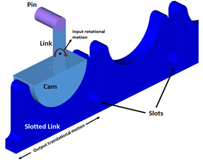
A slotted link mechanism (sometimes also referred to as a scotch-yoke mechanism) is a type of mechanism used to convert an input rotational motion into continuous or intermittent translational motion of a sliding link or yoke part. The motion is transferred via a contact force between parts of the mechanism that are in contact. Both normal and friction contact force may be responsible for the transfer of motion.
Such mechanisms find common application in valve actuators, air compressors, certain reciprocating and rotary engines, among others. The figure below illustrates a slotted link mechanism that will be modeled in this tutorial.