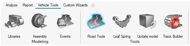
To visualize road graphics in MotionView, load the Vehicle
Tools Extension and open the Road Tools dialog. Figure 1. Road Tools Selection Menu
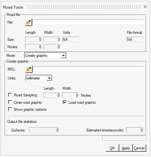
The Road option provides a way to create a surface graphic for the various Altair Road
Files.
From the dialog, select the desired road file. All the road types mentioned in the previous
sections except 3D Cleat can be visualized. The crg files must be chosen directly instead of
providing the rdf containing the crg.Figure 2. Road Dialog
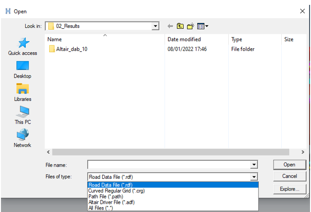
In the Road Tools dialog, the Road File path and the Road type must be chosen as shown in
the figure below. Figure 3. Road File Path and Type Selection
The MDL option allows the selection of the file path location where the created road
graphics are saved.
Road Sampling can be changed as per your requirement to reduce the time and detail level
for producing graphics.
If the [GRAPHICS] block is described in road file, it will be used for the road graphics
definition.
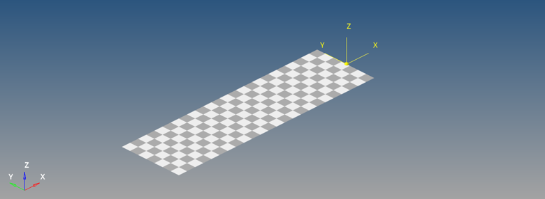
In the case of a FLAT road type, a checkered grid is created. The grid size is obtained
from the LENGTH and WIDTH value available in [GRAPHICS] block. The square size is obtained
from the ROAD_INCR value.
The road’s origin is shown by the marker in the figure below. If the ROAD_INCR is positive,
the grid is created in positive x direction. If negative, the grid is created in negative x
direction.Figure 4. Checkered Road