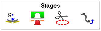
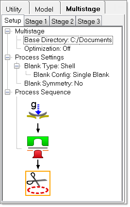
The multistage simulation for this tutorial uses the following forming sequence: Gravity, Double-Action Draw and Trimming.
Stage 1: Gravity
| 1. | On the Multistage tab, locate the forming template, and then double-click the Gravity tool: . . |
Gravity appears in the Process Sequence for your simulation:
| 2. | On the tree, right-click  , and then select Details from the context menu. The Stage 1 tab opens and displays the gravity settings. , and then select Details from the context menu. The Stage 1 tab opens and displays the gravity settings. |
| 3. | From the File menu, click Open. |
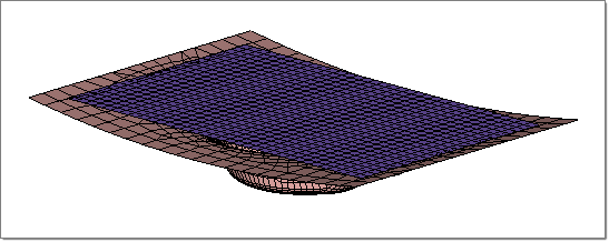
| 4. | Navigate to the model file, multistage_gravity_radioss.hf, and click Open. |
Note: The model files for this tutorial are located in the file mfs-1.zip in the subdirectory \hf\Incremental\. See Accessing Model Files.
The model on your screen should look something like this:
| 5. | From the tree in the User Process, check that the Blank and Die objects are pointing to their respective components. If not, under Blanks, right-click Blank, and then select Blank > Component. Do the same for the Die. Under Tools, right-click die, and then select component. |
The default settings for Material and Thickness appear under the Blank. To learn about modifying these settings, see HF-3010: User Process.
| 6. | From the top of the tree in the User Process, right-click Process: multistage_gravity_radioss, and then select Autoposition. |
| 7. | Right-click Process: multistage_gravity_radioss, and then select Create Input. The setup is captured and reflected in the tree. |
Stage 2: Double Action Draw
| 1. | Click the Setup tab, and then double-click the Forming tool:  . . |
The Forming tool appears below the Gravity tool and the Stage 2 tab appears:
| 2. | Right-click , and then select Details. The Stage 2 tab opens. |
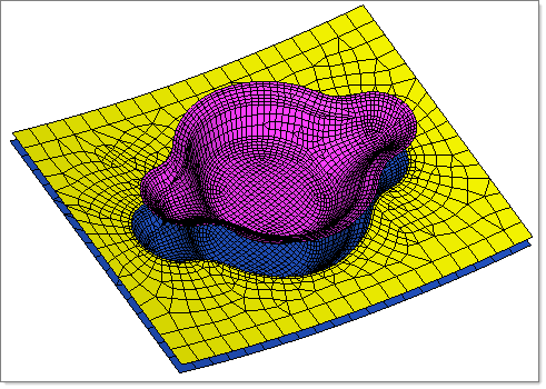
| 4. | Navigate to the model file multistage_double_action_draw_radioss.hf. |
The model on your screen should look something like this:
| 5. | On the tree, under Process: multistage_double_action_draw_radioss, right-click Process Type: > Forming > Double Action. |
| 6. | On the tree, under Tools, make sure that the die, binder and punch are pointing to the their corresponding components. If they are not, right-click die, and then select component > die. Do the same for the binder and punch. |
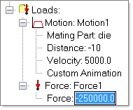
| 7. | On the tree, under Tools > Binder > Loads > Force: Force1, select Force:-1000.0, and then select the value -1000.0. Change the value to -250000.0, and then press Enter. |
Stage 3: Trimming
| 1. | Select the Setup tab, and then double-click the trimming tool:  . . |
The trimming tool appears in the Process Sequence:
| 2. | On the tree, right-click , and then select Details. The Stage 3 tab opens and displays the trim settings. |
| 3. | Select File > Import > Geometry. |
| 4. | On the the Import tab that appears, navigate to the model file, multistage_trim_line.igs. |
The geometry appears on your screen.
| 6. | On the Import tab, click Close to return to the Stage 3 tab. |
| 7. | On the tree under Blanks > Blank, right-click Trim Lines, and then select New. |
| 8. | Right-click Trim Line 1, and then select Select Lines... |
| 9. | In the graphics area, select the trim line on your screen, and then click proceed. |
| 10. | On the tree, right-click Trim Line1, and then select Outside. |
Simulating
| 1. | Select the Stage 1 tab. Moving to the this tab ensures the simulation starts from Gravity. |
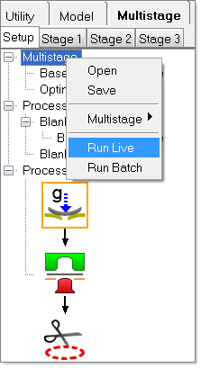
| 3. | On the tree, right-click MultiStage > Run Live. A pop up dialog appears asking if you want to run the process from Stage 1. Click Yes. |
The simulation of the multi-step forming sequence begins.
|