The Extract Thickness button opens the Extract Midsurface Thickness dialog, which is used to extract thickness from the midsurface onto the elements. This procedure automatically creates the necessary property cards and assigns them to the elements. Therefore, it eliminates the need to manually edit and assign property cards. Property cards are created with different colors so that grouping of elements becomes easier.
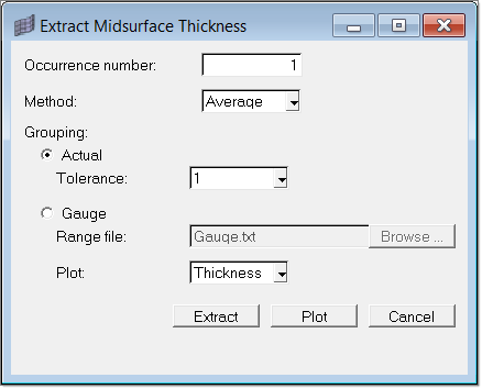
The following options are available in the Extract Midsurface Thickness dialog:
Option
|
Description
|
Occurrence number
|
Defines the symmetry in the multi-cavity mold. See About Occurrence Numbers for more information about occurrence numbers.
|
Method
|
Element thickness can be determined in the MPI 4.0 interface at element level, using one of the following methods:
|
|
Average
Estimates the thickness as the average of the three nodal thickness (T1 +T2 +T3) / 3.0.
|
|
Centroid
The thickness of the element at its centroid is taken as the element thickness.
|
|
Maximum
The maximum of the three nodal thicknesses is taken as the element thickness.
|
|
Minimum
The minimum of the three nodal thicknesses is taken as the element thickness.
|
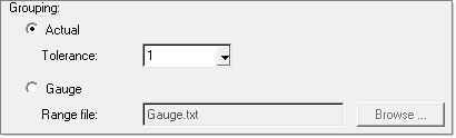
Grouping
|
Beyond a certain degree of accuracy, it may be meaningless to distinguish the thickness of two elements and thereby create two property cards. For instance, if you are meshing the part in mm, numerically it may not be necessary to distinguish between thickness value 1.00 and 1.01. It is more practical to take the thickness of both the elements as 1.00mm. The thickness grouping option provides this flexibility. There are two different ways this can be achieved.
|
|
Actual Tolerance
The decimal tolerance at which to round-off the thickness value assigned to an element.
|
|
Gauge File
The gauge file used to determine the element thickness. The gauge description uses the algorithm: all the elements falling within thickness range a to b will take the value c. That is if element thickness t is such that a <= t < b then thickness = c.
An example gauge file is shown below. If you use this file, an element with thickness 1.75 will be assigned the value 2.00, as its thickness falls between 0.00 and 4.00. The phrase "Number of Gauges" and the word "Gauges" are keywords.
# Thickness Lookup table
# Please follow the format shown below.
Number of Gauges
4
Gauges
Begin End Assigned Value
0.00 4.00 2.00
4.00 4.25 4.15
4.25 4.75 4.50
4.75 9.99 4.75
|
|
Plot
Select Thickness or Eccentricity
|
Extract
|
Extracts the thickness and plots the thickness distribution.
|
Plot
|
Plots the thickness distribution based on the element property cards. Therefore, you can inspect the thickness distribution of a mesh with hand-edited property cards.
|
Cancel
|
Closes the dialog.
|
See Also:
Moldflow Utility Menu


