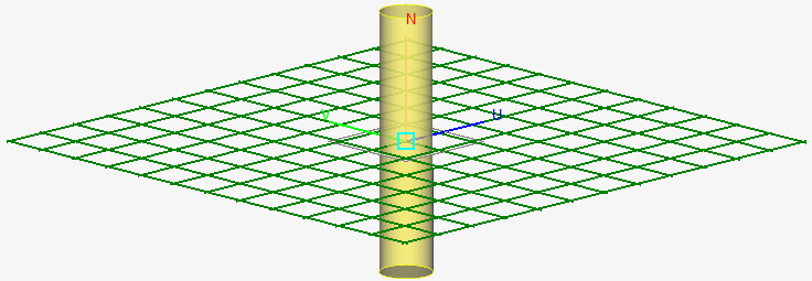
Excite a dipole made from a cylinder and add an edge port.
Create a cylinder.
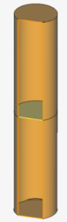
Split the cylinder to create two sections.
CADFEKO automatically adds a face on the split plane to keep the two split parts
as solid parts.
Figure 1. The preview of the split operation on the thick dipole.
Union the two sections to ensure the faces in the edge port belong to the same
part.
Delete the face on the split plane.
When specifying an edge port, all faces
bordering the edge must be specified in the edge port definition. Delete the
extra face created when the two sections were unioned. Deleting the face
results in a single region with only two faces bordering the edge.
Tip: Model the cylinder as Free Space (shell
object) to avoid the face.
Figure 2. Cutplane view of the thick dipole with face in the middle to be
deleted after Union.
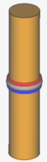
Add the edge port.
Specify the outer face of the one section as the positive
face. Specify the outer face of the second section as the negative face. The
result is an edge port which is not straight but closes on itself.
Figure 3. An edge port is added to the thick dipole. Note the edge closes
on itself.
Using an Edge Port with the FDTD solution
method
The following requirements must be met when using an edge port with the FDTD solution method:
All meshed port faces must lie in the same plane. Port faces which do not
lie in the same plane results in conflicting potentials at a point.
All meshed port faces must point in the same direction.
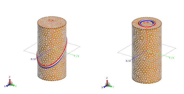
Figure 4. Examples of valid edge ports on a triangular mesh.
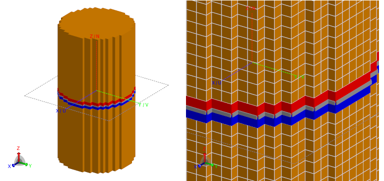
Figure 5. A valid edge port on a voxel mesh. Note the meshed port faces all lie in
the same plane.
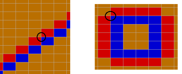
Figure 6. If a voxel mesh is applied to the same model as the top example and a
similar edge port is specified, it results in an invalid edge port as
displayed in the section views. The black circles indicate an example of a
point with conflicting potentials.