Creating a Braided Cable Shield Layer (Kley)
Create a single layer, braided (Kley) cable shield. The relevant braid parameters, weave metal and braid-fixing materials (optional) are specified and the Solver determines the frequency-dependent impedance (Zs + Zt) and admittance (Yt) matrix using the Kley formulation.
-
On the Cables tab, in the
Definitions group, click the
 Cable Shield icon.
-
On the Inner layer tab, on the Impedance
definition tab, from the Definition
method
drop-down list, select Braided (Kley).
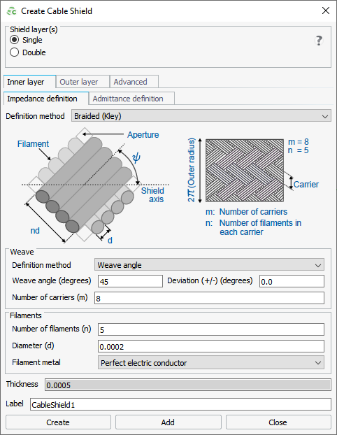
Figure 1. The Create Cable Shield dialog. -
Under Filaments, specify the following:
-
In the Filament metal
drop-down list, select one of the following:
- To create a filament consisting of PEC, select Perfect electric conductor.
- To create a filament consisting of a predefined metal, select the metal.
- To create a filament consisting of a metal, which is not yet
defined in the model, select the
 icon to define a metal or add a metal from the media
library.
icon to define a metal or add a metal from the media
library.
-
In the Filament metal
drop-down list, select one of the following:
Note: The Thickness of a Kley
shield layer is 2.5 times the filament diameter (d).
-
On the Inner layer tab, on the Admittance
definition tab, from the Definition
method
drop-down list, select Same as impedance
definition to use the Kley
formulation for the admittance matrix.
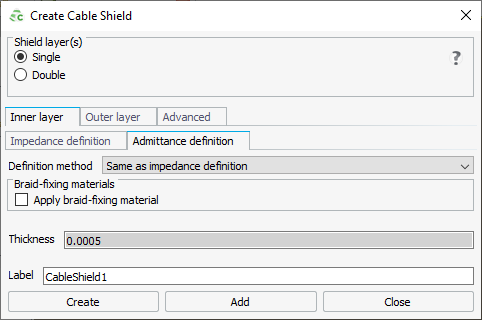
Figure 2. The Create Cable Shield dialog. -
Under Braid-fixing materials, select one of the
following:
- To apply an inside and outside braid-fixing material, select the
Apply braid-fixing material check box.
- To add an inside and outside braid-fixing material consisting of a predefined dielectric, select the dielectric.
- To add an inside and outside braid-fixing
material consisting of a dielectric, which is not yet defined in
the model, click the icon to define a dielectric or add a dielectric from the
media library.
- To remove the braid-fixing material, clear the Apply braid-fixing material check box.

Figure 3. A 3D representation of a cable containing a braid (on the left) and a cross-section of the cable showing the inside braid-fixing material and the outside braid-fixing material (on the right). - To apply an inside and outside braid-fixing material, select the
Apply braid-fixing material check box.