Block Category: Real Time
Description: The MCC Input block configures input channels for any Measure Computing board using the universal driver. It defines the base address and channel number to which the pulse width modulated waveform is sent.

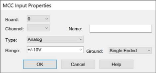
Board: Selects the installed Measurement Computing board. Text that describes the board will appear to the right.
Channel: Indicates the analog, digital, or counter channel. For each 8255 unit, channels 0 – 7 correspond to Port A; channels 8 – 15 correspond to Port B; channels 16 – 23 correspond to Port C. Note that multiple digital devices are treated like one large device. Thus, digital channel 24 corresponds to Port A bit 0 on the second 8255 digital device.
Ground: Indicates whether the I/O board is single ended (that is, single ground for all channels) or differential (that is, floating ground). If you choose differential, the channel count is adjusted to reflect the channel type.
Name: Specifies a unique name for your MCC Input block
Range: Indicates the voltage range for the I/O board.
Type: Indicates whether the board is analog, digital, or counter channels. The channel count is adjusted to reflect the channel type.