Block Category: Real Time
Description: Currently, only the MFIO-3A board from Precision Micro Dynamics is supported.
Because the MFIO-3A board has quadrature encoder inputs, to access all three encoder inputs, use three encoder blocks.
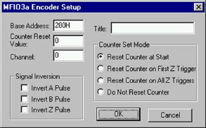
Title: Specifies a name for the encoder channel that is accessed with the encoder block. By giving unique names to different encoder inputs, you can easily distinguish between them.
Base Address: Indicates the I/O port register address through which the real-time driver commands the board. Enter the base address as a hexadecimal number, followed by an “H.”
Counter Reset Value: Resets the value of the index pulse on the occurrence of the index pulse and according to the counter set mode.
Channel: Specifies a number that corresponds with the channel number on the screw terminal or termination panel supplied with your MFIO-3A board. Embed uses channel 0 as the first channel, even if the documentation supplied by the board vendor describes the first channel as channel 1.
Signal Inversion: Each channel on the MFIO-3A board has an A-, B-, and Z-axis. You can invert one or more axes to get phasing information. The two pulses, A and B, are shifted by a quarter of a cycle with respect to each other. The shift between the two signals enables the controller or the simulation to determine the direction of rotation, according to whether pulse A leads pulse B, or vice versa.
Counter Set Mode: Resets the counter on your MFIO-3A board to the value specified in the Counter Reset Value box. You have the following choices:
•You can reset the counter at the start of the simulation.
•You can reset the counter at the first occurrences of the index pulse (which is also known as the Z trigger).
•You can reset the counter at every occurrence of the index pulse.
You can alternatively not ever reset the counter.