Prerequisite: To use the Altair Embed Add-On DLL wizard (commonly referred to as the Embed DLL wizard), Microsoft Visual Studio (MSVS) must be installed on your computer. See the Embed Installation Guide in your Embed-installation-folder/doc for installation instructions.
A quick way to generate the skeletal code for a custom block and create a simple dialog for the block is to use the Embed DLL Wizard in conjunction with MSVS.
The Embed DLL wizard performs the following functions:
•Creates all the source files, including CPP, H, and RC files
•Adds the source, resource, and VISSIM64.LIB files to the project file
•Specifies the number of inputs, outputs, connector label names for the custom block
•Adds sample code to generate a customizable MFC dialog that can be edited in MSVS
To run VSIX to install the Embed DLL wizard in MSVS
1. Open File Explorer and go to your Embed install folder.
2. Double-click dllWiz20.vsix (if you have MSVS 2019) or dllWiz22.vsix (if you have MSVS 2022) to install the Embed DLL wizard in MSVS.
To create a block and corresponding dialog with the Embed DLL wizard
1. Start MSVS.
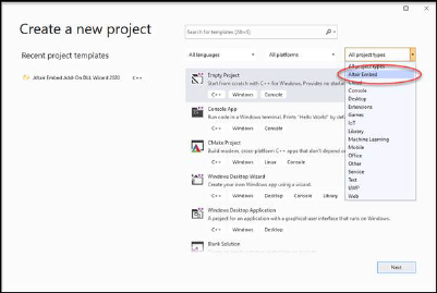
2. Choose File > New > Project.
3. In the Create a new project dialog, set the Project Type to Altair Embed.
4. Click Next.
5. In the Configure your new project dialog, update the project name, location the project is stored, and solution name, accordingly. For more information on these settings, see Microsoft Visual Studio documentation.
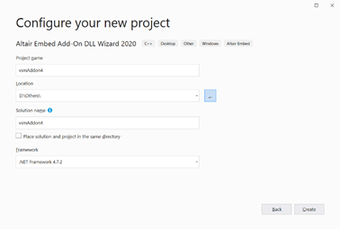
6. Click Create, or press ENTER.
The Embed DLL wizard starts up.
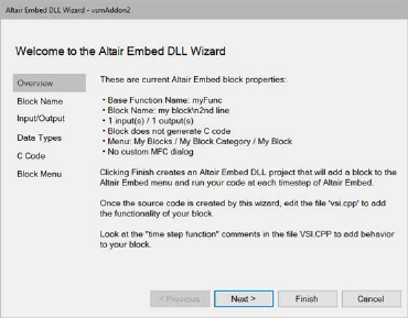
7. This dialog contains default Embed block properties to review and edit.
8. Click Next or select Block Name.
The following dialog appears:
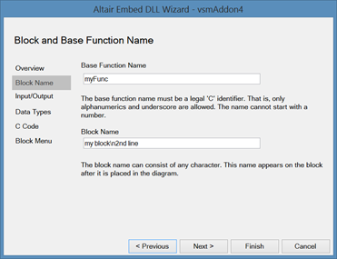
9. To edit the block and function name:
a. In the Base Function Name box, enter the base name of the function. The name you enter appears in the title bar of the dialog that corresponds to the custom block you are creating.
b. In the Block Name box, enter the name of the block. The name you enter appears on the block. For long block names, use “\n” to span the name over multiple lines. For example, My Block\nIs Awesome.
c. For consistency, the block name you specify here should also be used in step 15.
d. Click Next or Input/Output.
The following dialog appears:
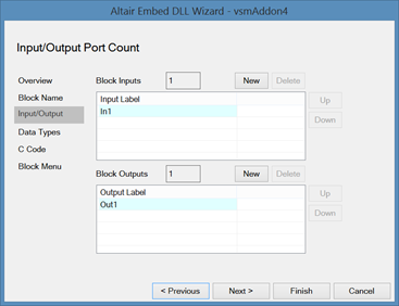
10. This dialog lets you label the input and output connectors on the block. Although it is recommended that you label the connectors, it is not required. If you choose not to label the connectors, simply enter the connector count in the Block Inputs and Block Outputs boxes. To label the connectors, do the following:
a. In the Input Label window, enter the connector name and click New. The name appears in the list box. Repeat these steps for each label. Connectors are labeled from top to bottom. To re-arrange the labels in the list box, use the Up and Down buttons.
b. In the Output Label window, enter the connector name and click New. The name appears in the list box. Repeat these steps for each label. Connectors are labeled from top to bottom. To re-arrange the labels in the list box, use the Up and Down buttons.
11. Click Next or Data Types.
The following dialog appears:
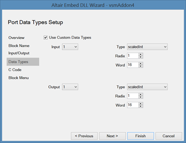
12. To create custom data types for your input and output connectors, activate Use Custom Data Types and do the following:
a. Input connectors: In the Input box, select the pin number; in the Type box, select the data type. If you choose matrix or scaled integer, enter the dimension or radix and word size.
b. Output connectors: In the Output box, select the pin number; in the Type box, select the data type. If you choose matrix or scaled integer, enter the dimension or radix and word size.
13. When done, click Next or C Code.
The following dialog appears:
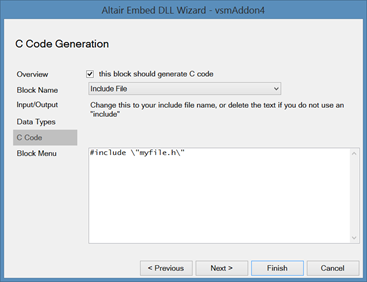
14. To generate C code for your custom block, activate This block should generate C code and do the following:
a. In the list box, click the DOWN ARROW to see code generation events to which your block can respond. The window below the list box shows the string to be included in your code. To edit the string, position the pointer in the window and click the mouse. If you do not want a particular string to be included in your code, delete it from the window.
b. Click Next or Block Menu.
The following dialog appears:
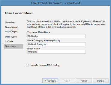
15. This dialog lets you choose where your block appears in an Embed menu. Note that the block is not accessible from Embed until after you add the corresponding DLL to the Embed initialization file.
a. In Top Level Menu Name, specify the name of the menu in Embed’s menu bar under which the category containing your block will appear. If you want to use the standard Blocks menu, enter &Blocks.
b. In Block Category Name, specify the name of the category under which your block will appear. You can use an existing category name (for example, Linear Systems or Arithmetic) or you can enter a new name.
c. In Block Name, specify the name of your block. For consistency, you should use the block name specified in step 9.
d. To generate an MFC dialog for your block, activate Include Custom MFC dialog.
e. Click Finish.
A new project is created. The files of interest are VSI.CPP, VSMDIALOG.CPP, and VSMDIALOG.H.
16. To build a DLL, in Microsoft Visual Studio, choose Build > Build projectname.DLL, where projectname is the name specified in step 3.
17. If you generated an MFC dialog in step 15d, you can customize the dialog box using Microsoft Visual Studio.
18. Add the block to an Embed menu or bind the DLL to a userFunction block.