Category: Toolbox > eDrives > eMotors (Legacy) > Loads
Description: The Rotational Load block represents a mechanical rotational load model.
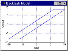
The Rotational Load block models the dynamic and static behavior of a single degree of freedom, rotational rigid body connected by a linkage mechanism. The Rotational Load block provides flexible definition over a variety of generic load configurations used for motor applications in speed, torque, and position control. The generic linkage ratio represents any type of mechanical advantage that multiplies either torque or speed. This represents a large class of mechanisms, including gear trains, pulleys, and levers. The linkage can either include or exclude hysteretic backlash.
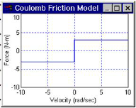
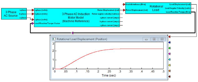
The Rotational Load block requires connection with a motor block model to complete the load dynamics. Load reaction torques are reflected back into motor dynamics using a load reaction torque vector wire connection. Besides hysteresis, the Rotational Load block includes Coulomb friction, viscous friction, load inertia, torsional spring torque, spring preload torque, and hard stops. These properties can be used simultaneously; or by choosing a 0 value for a particular property, it can be eliminated from the Rotational Load block. A disturbance torque input is provided that may be applied from other system component models, such as bearing noise, and wind gust torque models.

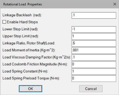
Enable Hard Stops: When activates, this block enables hard stops on rotational motion at the specified upper and lower stop limits.
Linkage Backlash: Introduces hysteretic backlash in linkage mechanism. Enter 0 for no backlash.

Linkage Ratio, Rotor Shaft/Load: Defines the mechanical advantage factor between the rotor shaft and load. Enter 1 for direct coupling between rotor shaft and rotational load; enter a number less than 1 to multiply torque; and enter a number greater than 1 to multiply speed.
Load Moment of Inertia: Indicates the inertia of load about the axis of rotation.
Load Viscous Damping Factor: Indicates the proportional factor that relates the angular velocity to the dissipative torque. Enter 0 for no viscous damping.
Load Coulomb Friction Magnitude: Indicates the constant directional sensitive torque (Coulomb model). Enter 0 for no Coulomb loading.

Load Spring Constant: Indicates the proportional spring factor that relates the angular position of the load to the restoring torque. Enter 0 if there is no torsional spring in the load.
Load Spring Preload Torque: Indicates the initial restoring (bias) torque introduced by load torsional spring. Enter 0 if there is no preload in the torsional spring.
Lower Stop Limit: Indicates the minimum hard stop limit. This parameter is available only when Enable Hard Stops is activated.
Upper Stop Limit: Indicates the maximum hard stop limit. This parameter is available only when Enable Hard Stops is activated.
Diagram name: Rotational Load
Location: Examples > eDrives > eMotors (Legacy) > Loads
The Rotational Load block is configured with a torsional spring with a 1 N-m/rad spring constant. The motor is started and allowed to settle to its final equilibrium position at 0 velocity. Since the spring constant is unity, the final angle of the shaft is a direct measure of the output torque in N-m.
