Category: Toolbox > eDrives > eMotors (Legacy) > Sensors
Description: The Rotary Servo Potentiometer block models the behavior of a servo potentiometer in terms of linearity and wiper noise. A rate estimator is used to switch wiper noise off at zero velocity. Hard stops are provided.

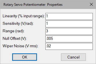
Linearity: Specifies the maximum deviation from true linear response in terms of a percentage of input range. A curvilinear distortion, symmetric about null is used to model non-linearity (S-curve).
Null Offset: Indicates the offset voltage at 0 input position.
Range: Indicates the total angular stroke of the potentiometer. If the input exceeds the allowable range, the output is limited to a constant value as if a slip-clutch coupling were used.
Sensitivity: Indicates the gain of the potentiometer.
Wiper Noise: Indicates the RMS voltage wiper electrical noise induced by contact motion between wiper and resistive element.
Diagram name: Rotary Servo Potentiometer
Location: Examples > eDrives > eMotors (Legacy) > Sensors
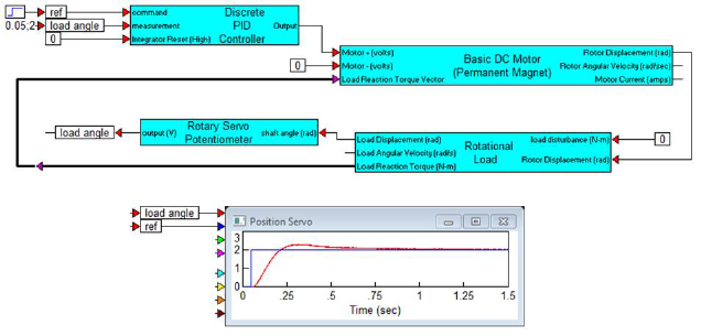
A fairly rough position control system is simulated using inexpensive components including a 10 to 1 gear reducer with ½ degree backlash, and a noisy servo potentiometer with 1% nonlinearity. The load has no intrinsic restoring forces. Consequently, a PID control block is used to configure a PI controller. The results show that even with the inexpensive components, decent positioning control can be obtained with minor overshoot.
