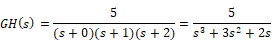
Gain compensator design can be performed interactively. For example, consider a system with an open-loop transfer function:
You are required to determine the appropriate gain compensation such that the phase margin is 45o.
To interactively design a gain compensator
1. Create the following system with a gain, transferFunction, and plot block.
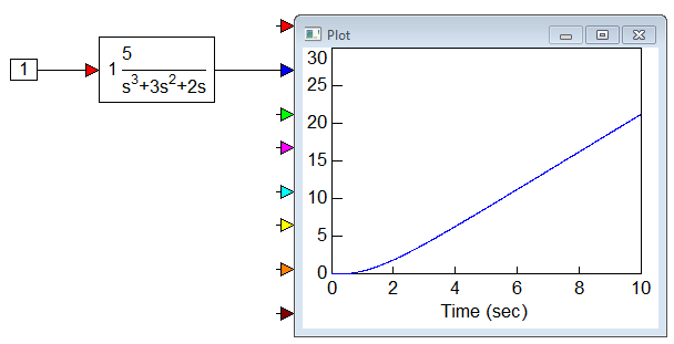
2. Enter the following polynomial coefficients to the transferFunction block:
•Numerator: 5
•Denominator: 1 3 2 0
Note: Always leave spaces between coefficient values.
3. Generate Bode and root locus plots.
4. Select the transferFunction block.
5. Choose Analyze > Compensator Design.
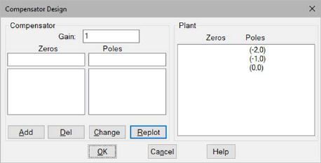
6. Click Replot. The Bode magnitude and phase plots, and the root locus plot are displayed. For this exercise, you can ignore the root locus plot.
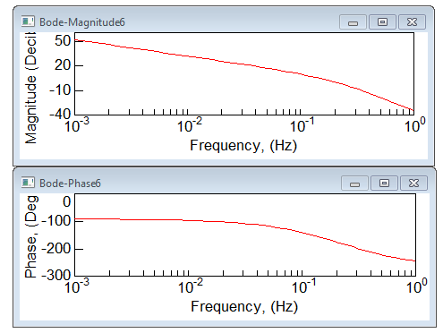
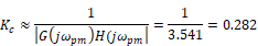
7. The phase margin of the uncompensated system is approximately 13o. For a phase margin of 45o, the corresponding ωpm from the Bode phase plot is 0.54 rad. For this frequency, the magnitude of the open-loop transfer function |G(jωpm)H(jωpm)| is 3.541. The compensator gain is:
8. In the Compensator Design dialog, do the following:
•In the Gain box, enter 0.282.
•Click Replot.
The updated Bode magnitude and phase plots are displayed.
If necessary, make minor adjustments to the gain value until the Bode plots indicate that the phase margin requirement is satisfied.