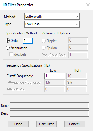
IIR filter design is the design of digital filters using Bessel, Chebyshev, Butterworth, or Inverse Chebyshev analog prototypes. To set up an IIR filter, click the IIR Filter button in the Transfer Function Properties dialog.
Epsilon and Ripple and Pass-Band Gain: Provide two alternate ways of specifying the behavior of a Chebyshev filter.
There is a fluctuation (or ripple) in the amount (or attenuation gain) of the Band Pass and Band Stop. The filter order affects the size of the ripple, and the filter can be tuned to minimize that ripple.
Epsilon refers to the error between the ideal filter and the actual filter, regardless of the ripple. Minimizing the epsilon provides a best fit filter.
Attenuation and Attenuation Frequency: For the attenuation characteristics of the filter, see Attenuation characteristics of the filter.
Cutoff Frequency: The low and high cut-off frequencies in the Frequency Specification box define the band edges. For Low Pass and High Pass filter types, there is only one cut-off frequency. For Band Pass and Band Stop filters, the low and high frequencies are both cut-off frequencies.
Bessel: Bessel filters are designed using Bessel polynomials. The Bessel filters are characterized by the property that the group delay is maximally flat at the origin of the s-plane. The step response of the Bessel filters exhibits very low overshoot and both the magnitude and impulse response exhibit gaussian decay as the filter order is increased.
Butterworth: Butterworth filters are characterized by the property that the magnitude characteristic is maximally flat at the origin of the s-plane. This means that all the existing derivatives of the magnitude response are 0 at the origin. Butterworth Low Pass filters are all-pole designs and have an attenuation of 3 dB at the critical frequency. The filter order completely specifies the filter and can either be explicitly provided or determined from the attenuation frequency and the attenuation level desired.
Chebyshev and Inverse Chebyshev: Characterized by the property that the peak magnitude of the approximation error is minimized over a prescribed band of frequencies. The magnitude is equi-ripple over the band of frequencies. For example, the magnitude oscillates between the maxima and minima of equal amplitude.
For Chebyshev filters, the band of the frequencies over which the error is minimized is the Pass Band. For inverse Chebyshev filters, the error is minimized over the Stop Band. The optimality property of the Chebyshev filters guarantees that no other all-pole filter offers equal or better performance in both the Pass and Stop bands. Inverse Chebyshev filters exhibit monotonic behavior in the Pass Band (maximally flat around the 0 frequency) and equi-ripple behavior in the Stop Band. The Low Pass filter has poles in the left half of the s-plane and 0s on the imaginary axis.
Specification Method: See How specification methods relate to analog filter prototypes for information on how the specification method relates to the analog filter prototypes.
Type: Indicates the band pass filter type.