Category: eDrives > Toolbox > Sensorless
Inputs:
•Ialpha: Motor current in alpha-axis measured from ADC channels.
•Ibeta: Motor current in beta-axis measured from ADC channels.
•Valpha: Motor voltage in alpha-axis measured from ADC channels.
•Vbeta: Motor voltage in beta-axis measured from ADC channels.
Outputs:
•Cos: Cosine of the estimated angular position.
•Sin: Sine of the estimated angular position.
Description: The AFT block tracks the flux vector while the drive is running. It estimates the rotor angular position and shaft speed. It also tracks and provides torque and flux of a motor while it is spinning in real time. The AFT block estimates stator phase resistance, and optionally, it can estimate rotor resistance for induction motors.
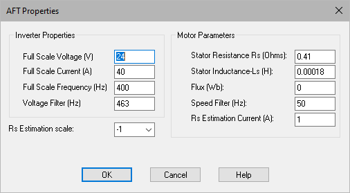
Full Scale Current (A): Specifies the full-scale current value for normalization.
Full Scale Frequency (Hz): Specifies the full-scale frequency value for normalization.
Full Scale Voltage (V): Specifies the full-scale voltage value for normalization.
Voltage Filter (Hz): Specifies the corner frequency for low-pass voltage filters used for estimation and power calculation.
Flux (Wb): Specifies the estimated or calculated magnetic flux for one phase. It is important to provide the proper value of the magnetic flux for PM motors.
Rs Estimation Current (A): Specifies a DC injection current, which is introduced to the d-axis current for estimation of stator resistance.
Speed Filter (Hz): Specifies the corner frequency for the speed estimator inside the AFT.
Stator Inductance-Lq (H): Specifies the measured q-axis stator inductance of the motor.
Stator Resistance Rs (ohms): Specifies the measured stator resistance of one motor phase.
Rs Estimation scale: Specifies an empirical scale, which calibrates the estimator close to the stator resistance. Change this value to obtain an Rs max value close to the actual measured stator resistance.