Target Category: Arduino
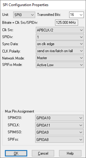
The SPI Config block lets you choose the hardware settings for the SPI Read for Arduino and SPI Write for Arduino blocks. Before you configure the SPI, it is a good idea to first insert a corresponding target configuration block in your diagram and specify the CPU device.
Bit Rate=SYSClk/SPIDiv: Displays the bit rate.
CLK Polarity: Clocks the polarity. You have two choices: Send on rise/Latch on fall and Send on fall/Latch on rise.
Mux Pin Assignment: Sets the external pins used to carry the SPI signals. Click here for Arduino pin mapping. The on-chip Slave Select (SS) pin is available in Slave network mode only.
Network Mode: Sets the mode to master or slave. In Master network mode, the SS pin is selected in the SPI Write for Arduino block.
SPIDiv: Sets the SPI bit rate. Select from the following:
|
SPIDiv |
SPI Bit rate (Hz) |
SYSClk (Hz) |
|
2 |
8000000 |
16000000 |
|
4 |
4000000 |
16000000 |
|
8 |
2000000 |
16000000 |
|
16 |
1000000 |
16000000 |
|
32 |
500000 |
16000000 |
|
64 |
250000 |
16000000 |
|
128 |
125000 |
16000000 |
Sync Data: Synchronizes the data on the clock edge or ½ cycle before clock edge.
|
Sync Data (CPHA) |
CLK Polarity (CPOL ) |
SPI Mode |
|
on clock edge (0) |
Send on rise/Latch on fall (0) |
MODE 0 |
|
½ cycle before clock edge (1) |
Send on rise/Latch on fall (0) |
MODE 1 |
|
on clock edge (0) |
Send on fall/Latch on rise (1) |
MODE 2 |
|
½ cycle before clock edge (1) |
Send on fall/Latch on rise (1) |
MODE 3 |
Unit: Specifies the unit number.