Target Category: C2407, F281X
Target Sub-Category: PWM
Description: There are four timers on the 2407, and each one has a PWM. For each PWM, you can specify the timer, timer rate, and timer period. Together, they provide the base frequency for the PWM. The input pin represents the fraction of ON time for the PWM pulse. A value of 0.99997 provides 100% ON time; a value of 0 provides no ON time.
Interactive mode: In this mode, the Duty Cycle input pin is active; however, all parameters in the dialog are inactive except Timer Source.
Additional information: Creating phase-shifted PWM signals.
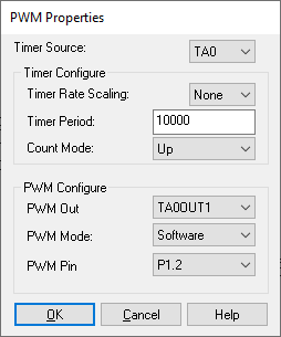
Count Mode: Specify one of four modes: up and down; up; hold; or TDIR control. Do not specify hold or TDIR control.
Initial Timer Count: Specifies the initial count for the timer. The timers start in numerical order, one after the other with no intervening instructions. Order placement on screen will have no effect.
Timer Period: In conjunction with Timer Rate Scaling, determines the frequency of the PWM waveform. For example, if the base clock rate is 32 MHz and the Timer Rate Scaling is 1/32, the effective clock rate is 1 MHz.
If Timer Period is set to 10, the output PWM frequency is 1/10 the effective clock rate of 1 MHz (100 kHz). However, this is a poor example since if Timer Period is set to be only 10, the output PWM frequency can only be varied in steps of 10%.
You must set Timer Rate Scaling and Timer Period in such a way that the desired output PWM frequency is obtained, while retaining fine control over the output duty cycle.
See Texas Instruments documentation for more information.
Timer Rate Scaling: In conjunction with Timer Period, determines the base PWM frequency. Select from available fractional timer rate multipliers to reduce the timer rate. Fractional rates of up to 1/128th the basic rate are possible. See Texas Instruments documentation for more information.
Timer Source: Specifies the timer source. If you choose the same timer for each PWM, then you must also choose the same timer rate and timer period for each PWM. There is a one-to-one correspondence between each EVM timer and the PWM output. For example, PWM1 uses Timer 1 and so on.