JointRRR
Planar revolute - revolute - revolute joint aggregation (no constraints, no potential states)
![]()
Library
Modelica/Mechanics/MultiBody/Joints/Assemblies
Description
This component consists of 3 revolute joints with parallel axes of rotation that are connected together by two rods, see the default animation in the following figure (the axes vectors are not part of the default animation):
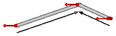
This joint aggregation introduces neither constraints nor state variables and should therefore be used in kinematic loops whenever possible to avoid non-linear systems of equations. It is only meaningful to use this component in planar loops. Basically, the position and orientation of the 3 revolute joints as well as of frame_ia, frame_ib, and frame_im are calculated by solving analytically a non-linear equation, given the position and orientation at frame_a and at frame_b.
Connector frame_a is the "left" side of the first revolute joint whereas frame_ia is the "right side of this revolute joint, fixed in rod 1. Connector frame_b is the "right" side of the third revolute joint whereas frame_ib is the "left" side of this revolute joint, fixed in rod 2. Finally, connector frame_im is the connector at the "right" side of the revolute joint in the middle, fixed in rod 2.
The easiest way to define the parameters of this joint is by moving the MultiBody system in a reference configuration where all frames of all components are parallel to each other (alternatively, at least frame_a, frame_ia, frame_im, frame_ib, frame_b of the JointRRR joint should be parallel to each other when defining an instance of this component).
Basically, the JointRRR model consists internally of a universal - spherical - revolute joint aggregation (= JointUSR). In a planar loop this will behave as if 3 revolute joints with parallel axes are connected by rigid rods.
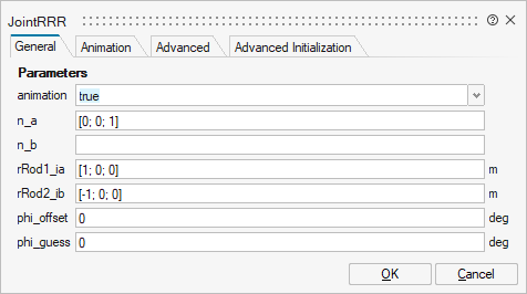
Parameters
| Name | Label | Description | Data Type | Valid Values |
|---|---|---|---|---|
mo_animation | animation | = true, if animation shall be enabled | Scalar | true |
mo_n_a | n_a | Axes of revolute joints resolved in frame_a (all axes are parallel to each other) | Vector of size 3 | |
mo_n_b | n_b | Axis of revolute joint fixed and resolved in frame_b | Vector of size 3 | |
mo_rRod1_ia | rRod1_ia | Vector from origin of frame_a to revolute joint in the middle, resolved in frame_ia | Vector of size 3 | |
mo_rRod2_ib | rRod2_ib | Vector from origin of frame_ib to revolute joint in the middle, resolved in frame_ib | Vector of size 3 | |
mo_phi_offset | phi_offset | Relative angle offset of revolute joint at frame_b (angle = phi(t) + from_deg(phi_offset)) | Scalar | |
mo_phi_guess | phi_guess | Select the configuration such that at initial time |phi(t0) - from_deg(phi_guess)| is minimal | Scalar | |
mo_e_a | e_a | Unit vector along axes of rotations, resolved in frame_a | Vector of size 3 | |
mo_e_ia | e_ia | Unit vector along axes of rotations, resolved in frame_ia | Vector of size 3 | |
mo_e_b | e_b | Unit vector along axes of rotations, resolved in frame_b, frame_ib and frame_im | Vector of size 3 |
| Name | Label | Description | Data Type | Valid Values |
|---|---|---|---|---|
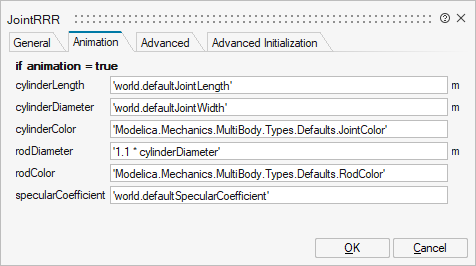
mo_cylinderLength | cylinderLength | Length of cylinders representing the revolute joints | Scalar | |
mo_cylinderDiameter | cylinderDiameter | Diameter of cylinders representing the revolute joints | Scalar | |
mo_cylinderColor | cylinderColor | Color of cylinders representing the revolute joints | Vector of size 3 | |
mo_rodDiameter | rodDiameter | Diameter of the two rods connecting the revolute joints | Scalar | |
mo_rodColor | rodColor | Color of the two rods connecting the revolute joint | Vector of size 3 | |
mo_specularCoefficient | specularCoefficient | Reflection of ambient light (= 0: light is completely absorbed) | Scalar |
| Name | Label | Description | Data Type | Valid Values |
|---|---|---|---|---|
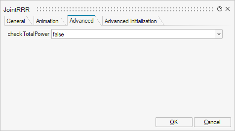
mo_checkTotalPower | checkTotalPower | = true, if total power flowing into this component shall be determined (must be zero) | Scalar | true |
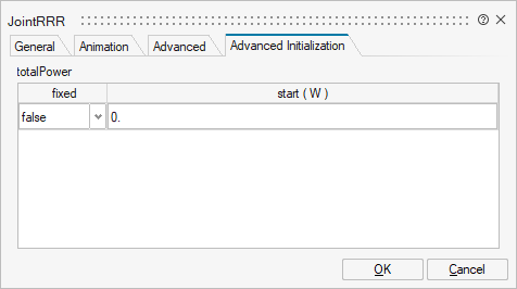
| Name | Label | Description | Data Type | Valid Values |
|---|---|---|---|---|
mo_totalPower | totalPower | totalPower | Structure | |
mo_totalPower/fixed | fixed | Cell of scalars | true | |
mo_totalPower/start | start | Cell of scalars |
Ports
| Name | Type | Description | IO Type | Number |
|---|---|---|---|---|
frame_a | implicit | Coordinate system fixed to the component with one cut-force and cut-torque | input | 1 |
frame_b | implicit | Coordinate system fixed to the component with one cut-force and cut-torque | output | 1 |
frame_ia | implicit | Coordinate system at origin of frame_a fixed at connecting rod of left and middle revolute joint | input | 2 |
frame_ib | implicit | Coordinate system at origin of frame_b fixed at connecting rod of middle and right revolute joint | output | 2 |
frame_im | implicit | Coordinate system at origin of revolute joint in the middle fixed at connecting rod of middle and right revolute joint | output | 3 |
axis | implicit | 1-dim. rotational flange that drives the right revolute joint at frame_b | input | 3 |
bearing | implicit | 1-dim. rotational flange of the drive bearing of the right revolute joint at frame_b | output | 4 |