Automat
This block enables the construction of hybrid automata. For example, the discrete part of a hybrid system can be defined via modes and transitions between modes, and the continuous-time part can be defined via Differential Algebraic Equations.
![]()
Library
Activate/Hybrid
Description
The Automat block provides a facility to construct hybrid automata such as a hybrid system whose discrete part is defined by modes and transitions between modes, and the continuous part is defined via DAE (Differential Algebraic Equations).
The Automat block provides a switching mechanism between subsystems corresponding to control modes of an automaton. Subsystems are constructed in such a way that they have the state vector as input (coming from the automaton's second output port) and compute the flow and jump functions (zero-crossing) and pass them back to the automaton block. The state variables are defined in the automaton block and the subsystems are static memory-less functions.
Suppose that a hybrid automaton consists of M control modes. The continuous-time dynamics in mode i is defined with DAE :
where i is in [1...M] and the dimension of x is N for any i in [1...M]. Suppose that in control mode i, there are Z_i jump conditions indicating jumps toward other modes. The jump conditions are defined by functions :
where j is in [1...Z_i]. When a jump function changes sign and becomes positive, a mode transition will happen. When k-th transition function becomes positive, a transition from mode "i" to mode "k" happens and state vector x is reset to :
In order to develop an automaton containing a mode with multiple reset functions, the value of the current and previous active modes might be useful. These values are available at the first output port of the block.
For more details, please refer to the section on Hybrid Automata in the Extended Definitions for Advanced Users.Parameters

| Name | Label | Description | Data Type | Valid Values |
|---|---|---|---|---|
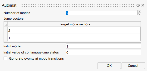
NMode | Number of modes | Number of modes used in the state chart that is defined by the automaton. | Number | |
jumps | Jump vectors | List of possible destination modes for each mode. | Structure | |
jumps/tmodev | Target mode vectors | Ordered list of destination modes for a given mode. For example, if in mode "i" (i-th line of this block parameter), and the list is composed of [j,k,m], and if the second zero-crossing of the i'th subsystem crosses the zero in the negative to positive direction, then a transition will occur from mode "i" to " k". | Cell of vectors | |
Minitial | Initial mode | Active mode at the initial time. | Scalar | |
X0 | Initial value of continuous-time states | State values at the initial time. | Vector | |
outevent | Generate events at mode transitions | Generates events when a jump function changes sign and becomes positive. A mode transition follows. | Number | 0 |
Ports
| Name | Type | Description | IO Type | Number |
|---|---|---|---|---|
Port 1 | explicit | Input vectors for the different modes (subsystems) of the model. The automaton block has M vector input ports corresponding to M modes or subsystems of the automaton. The input port i which is the output of the i-th subsystem is a vector of size 2*N+Zi. Each input is composed of several elements: the dynamic behavior of the model, the reset functions, and the transition functions for that mode. The first N elements of the Input_i are the continuous-time dynamics. The dynamics of the system in the control mode i is described by a smooth index-1 DAE, i.e., The next N elements of Input_i are the values used to reset the continuous-time state when a transition to control mode i is activated. The next Z_i elements of Input_i are the jump or zero-crossing functions. If the j-th zero-crossing function of mode i crosses zero with negative to positive direction, a transition to j-th destination mode happens. When the control mode is i, all zero-crossing surfaces of that mode should have negative values. | input | NMode |
Port 2 | explicit | Output vector comoposed of the active mode and the previous mode. This output port is a vector of size two. The first element of this output is the current active mode and the second element is the previous modes, i.e., | output | 1 |
Port 3 | explicit | Output vector of the active subsystem. The second output port is a vector of size 2N. The first N element is the state vector and the second N element is the first time derivative of the state vector, i.e., | output | 2 |
Port 4 | activation | Whenever a mode transition happens, an event is trigered at this output event port. This event is useful when an event is needed to activate or initialize a part of the subsystem not included in the internal dynamics of the automaton block. | output | outevent |
Advanced Properties
| Name | Value | Description |
|---|---|---|
always active | yes | |
direct-feedthrough | no | |
zero-crossing | yes | |
mode | yes | |
continuous-time state | Depends on block parameters | |
discrete-time state | no |