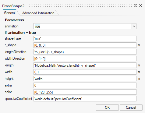
FixedShape2
Visualizing an elementary shape with dynamically varying shape attributes (has two frame connectors)
![]()
Library
Modelica/Mechanics/MultiBody/Visualizers
Description
Model FixedShape2 defines a visual shape that is
shown at the location of its frame_a. This model is identical
to FixedShape with the only difference that an
additional frame_b is present which is parallel to frame_a.
This makes it more convenient to connect several visual
shapes together when building up more complex visual
objects. All describing data such as size and color can vary dynamically by
providing appropriate expressions in the input fields of the
parameter menu. The only exception is parameter shapeType
that cannot be changed during simulation.
The following shapes are currently supported via
parameter shapeType (e.g., shapeType="box"):
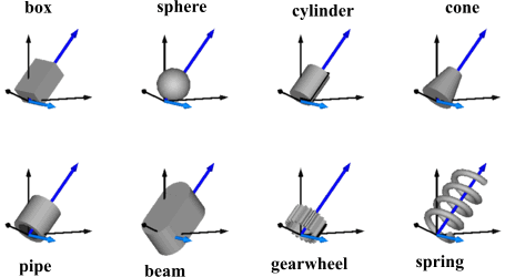
The dark blue arrows in the figure above are directed along
variable lengthDirection. The light blue arrows are directed
along variable widthDirection. The coordinate systems
in the figure represent frame_a of the FixedShape component.
Additionally, external shapes can be specified as (not all options might be supported by all tools):
- "1", "2", ...
define external shapes specified in DXF format in files "1.dxf", "2.dxf", ... The DXF-files must be found either in the current directory or in the directory where the Shape instance is stored that references the DXF file. This (very limited) option should not be used for new models. Example:
shapeType="1". - "modelica://<Modelica-name>/<relative-path-file-name>"
characterizes the file that is stored under the location of the <Modelica-name> library path with the given relative file name. Example:
shapeType = "../../../../Resources/Data/Shapes/Engine/piston.dxf". - "file://<absolute-file-name>"
characterizes an absolute file name in the file system. Example:
shapeType="file://C:/users/myname/shapes/piston.dxf".
The supported file formats are tool dependent. Most tools support at least DXF-files but may support other format as well (such as stl, obj, 3ds). Since visualization files contain color and other data, the corresponding information in the model is usually ignored. For information about DXF files, see Wikipedia. As a default it is assumed that the DXF coordinates are in the "frame_a"-system and in meters, and that the 3dfaces are two-sided. Some tools support only 3dface (for geometry) and layer (for advanced coloring).
The sizes of any of the above components are specified by the length, width and height variables. Via variable extra additional data can be defined:
| shapeType | Meaning of parameter extra |
|---|---|
| "cylinder" | if extra > 0, a black line is included in the cylinder to show the rotation of it. |
| "cone" | extra = diameter-left-side / diameter-right-side, i.e., extra = 1: cylinder extra = 0: "real" cone. |
| "pipe" | extra = outer-diameter / inner-diameter, i.e, extra = 1: cylinder that is completely hollow extra = 0: cylinder without a hole. |
| "gearwheel" | extra is the number of teeth of the (external) gear. If extra < 0, an internal gear is visualized with |extra| teeth. The axis of the gearwheel is along "lengthDirection", and usually: width = height = 2*radiusOfGearWheel. |
| "spring" | extra is the number of windings of the spring. Additionally, "height" is not the "height" but 2*coil-width. |
| external shape | extra = 0: Visualization from file is not scaled. extra = 1: Visualization from file is scaled with "length", "width" and "height" of the shape |
Parameter color is a vector with 3 elements, {r, g, b}, and specifies the color of the shape. {r, g, b} are the "red", "green" and "blue" color parts. Note, r, g, b are given as Integer[3] in the ranges 0 .. 255, respectively. The predefined type MultiBody.Types.Color contains a menu definition of the colors used in the MultiBody library together with a color editor.
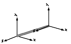
In the following figure the relationships between frame_a and frame_b are shown. The origin of frame_b with respect to frame_a is specified via parameter vector r.
Parameters
| Name | Label | Description | Data Type | Valid Values |
|---|---|---|---|---|
mo_animation | animation | = true, if animation shall be enabled | Scalar | true |
mo_shapeType | shapeType | Type of shape | String | |
mo_r_shape | r_shape | Vector from frame_a to shape origin, resolved in frame_a | Vector of size 3 | |
mo_lengthDirection | lengthDirection | Vector in length direction of shape, resolved in frame_a | Vector of size 3 | |
mo_widthDirection | widthDirection | Vector in width direction of shape, resolved in frame_a | Vector of size 3 | |
mo_length | length | Length of shape | Scalar | |
mo_width | width | Width of shape | Scalar | |
mo_height | height | Height of shape | Scalar | |
mo_extra | extra | Additional data for cylinder, cone, pipe, gearwheel and spring | Scalar | |
mo_color | color | Color of shape | Vector of size 3 | |
mo_specularCoefficient | specularCoefficient | Reflection of ambient light (= 0: light is completely absorbed) | Scalar |
| Name | Label | Description | Data Type | Valid Values |
|---|---|---|---|---|
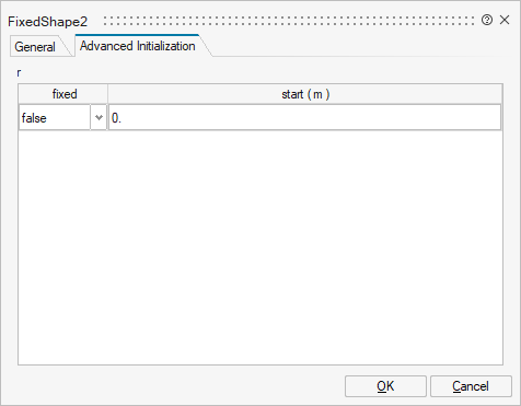
mo_r | r | r | Structure | |
mo_r/fixed | fixed | Cell of vectors of size 3 | true | |
mo_r/start | start | Cell of vectors of size 3 |
Ports
| Name | Type | Description | IO Type | Number |
|---|---|---|---|---|
frame_a | implicit | Coordinate system a (all shape definition vectors are resolved in this frame) | input | 1 |
frame_b | implicit | Coordinate system b | output | 1 |