3-Phase winding
1. Overview
In Motor Factory, two types of winding can be designed: Classical windings or hairpin winding types.
The design and the export of projects from FluxMotor® to Flux®2D can be done. However, no test is available while considering a hairpin winding topology.
Here is the home page for designing both classical and hairpin winding.
 |
|
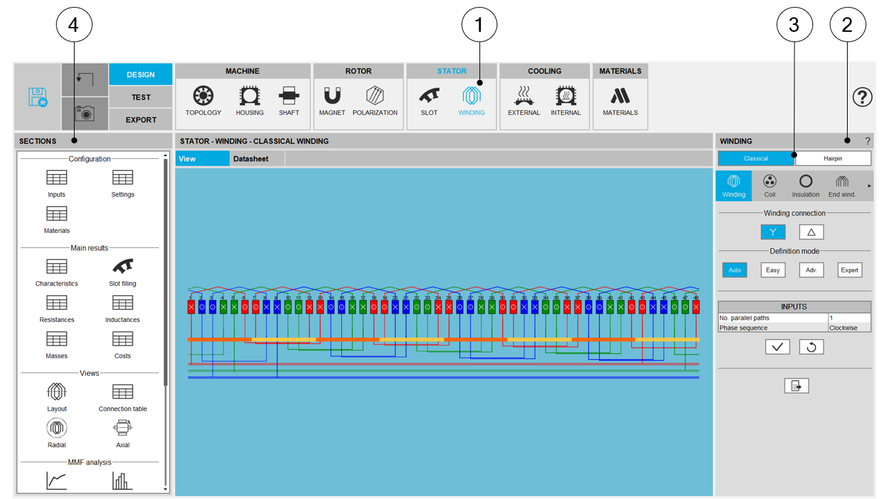
| WINDING design area – Area dedicated to classical windings | |
| 1 | Selection of the STATOR subset: WINDING panel (Click on the icon WINDING) |
| 2 | Winding input parameter panel dedicated for designing of the winding (either classical or hairpin technology windings) |
| 3 | Buttons to select the winding type “classical or hairpin” (here classical winding is selected – Highlighted in blue). |
| 4 | Shortcuts to easily navigate in the output sections |
The following sections describe the GUI dedicated to the classical and hairpin winding design.
The sections 2 & 3 are dedicated to classical winding design whereas sections 4 & 5 concerns the hairpin winding design.
2. Home page
For both types of winding, whether classical or hairpin, the home page characteristics are the same.
The following picture illustrates the main areas of the home page which is displayed for the classical winding.
 |
|
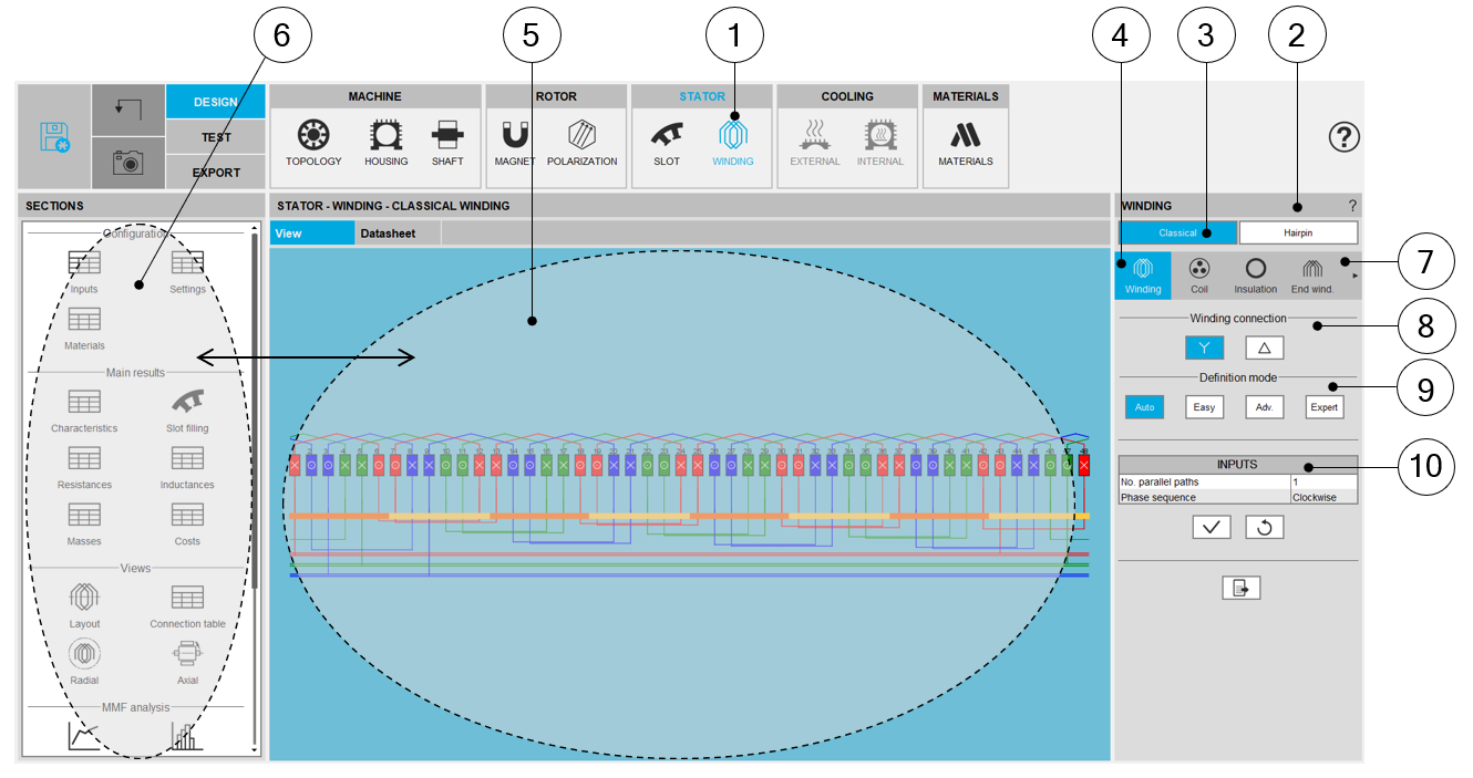
| WINDING design area – Classical winding - Overview | |
| 1 | Selection of the STATOR subset: WINDING panel (Click on the icon WINDING) |
| 2 | All the required user inputs to define the winding are available in the “WINDING” panel (right part). |
| 3 | Selection of the classical winding design (Highlighted in blue) |
| 4 | Winding settings allow describing the winding architecture |
| 5 | Once a winding is defined, the corresponding results are automatically
displayed in the form of a winding report. Visualization of the winding
characteristics (inputs, settings, materials, etc) are
possible. Scrollbars allow browsing the whole document rapidly and giving an overview of all the results. Using scrollbars, complete data can be accessed and visualized. |
| 6 | Shortcuts for displaying the corresponding section of the winding report. |
| 7 | A section scrolling bar allows choosing the section in which user inputs
are defined. Scrolling selection bar where Winding architecture, Coil, Insulation, End-winding, X-Factor and Potting sections can be selected |
| 8 | Choice of the winding connection: Y (Wye) or D (Delta) |
| 9 | Four modes of winding allow to define and build the winding architecture . |
| Auto | Automatic mode, used as default. |
| Easy | Easy mode, to choose solution among a list of choices. |
| Adv. | Advanced mode, to allow the user to define any specific input parameters. |
| Expert | Expert mode, to set the connection table. |
| 10 | User input parameter fields to enter the values according to the considered mode. |
3. Selection of sections
A scrolling selection bar helps to choose the section in which one can define the winding settings.
The winding can be built step by step. One can access the different sections by clicking on the following buttons:
- “Winding” to build the winding architecture
- “Coil” to set how the coil is defined and to see how the slots are filled.
- “Insulation” to define all the winding insulations
- “End winding” to define the topology and dimensions of the end-windings
- “X-Factor” to adjust phase resistance and end-winding inductance
- “Potting” to define the topology and dimensions of the potting around the end-winding
 |
|
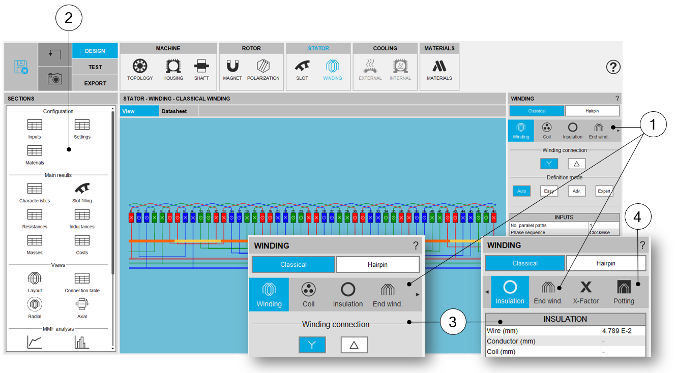
| Scrolling selection bar – Winding environment | |
| 1 | Scrolling selection bar, where Winding, Coil, Insulation, End-winding, X-Factor and Potting sections can be selected |
| 2 | Section data representing shortcuts for analyzing the input and output parameters |
| 3 | Arrow symbol allows the user to scroll the bar to reach other sections (on the right or the left) when needed |
| 4 | The bar slides on the right to allow reaching Potting section |
4. Information about Winding area GUI
 |
|
| WINDING design area – Information about GUI | |
| 1 | Shortcuts for displaying the corresponding chapter of the winding report. |
| 2 | In the current example, select “Layout” displays the layout of the winding. |
| 3 | Picture legends are available on the right part of the screen. |
| 4 | The legend can be folded right to save space: see below. |
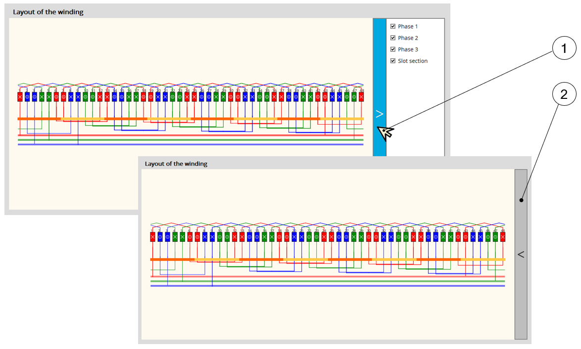 |
1 | Click on the blue band. |
| 2 | The legend is folded right: there is more space to analyze
pictures. Once the legend is folded, it is possible to unfold it by clicking on the grey band. |
|
| Process to fold or unfold the legends of graphics | ||
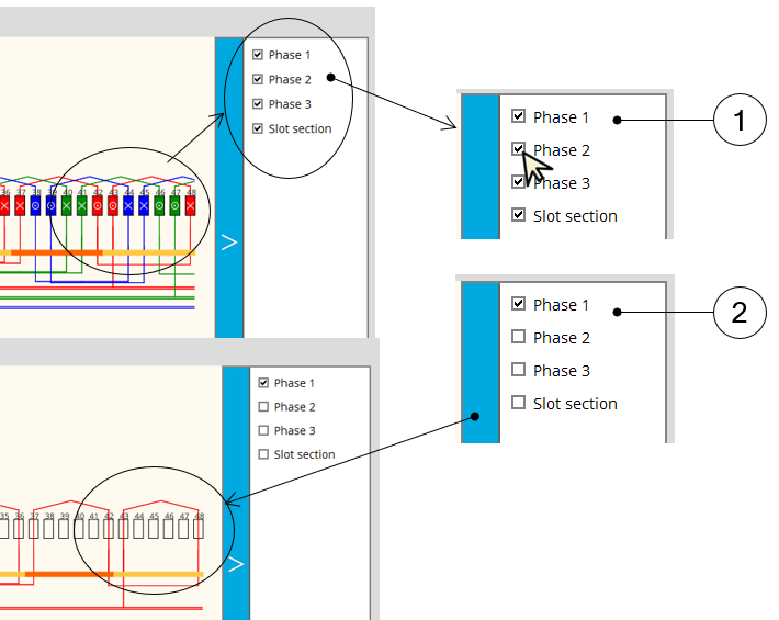 |
1 | All the legend items are checked. The corresponding phases and the slot
section are displayed. (With the phase color and sign to indicate the orientation of the electrical current). |
| 2 | Only the Phase 1 is checked.Phase 2 and 3 are no longer displayed along with the slot section. | |
| Process to manage visualization of phases on the picture | ||