The Linear Elastic Bonding Model
The bonds in the LEBM are modeled to be elastic, as the name of the model implies, providing a distinct type of behavior from that of the Bonding and Bonding V2 models. The theory presented in the articles Comparative Study of Different Discrete Element Models and Evaluation of Equivalent Micromechanical Parameters by J. Rojek et al. (2012) and Advances in the Development of the Discrete Element Method for Excavation Processes by C. A. Labra (2012) served as the foundation for the LEBM's implementation in EDEM. It is recommended that you refer to the aforementioned paper and thesis for an in-depth description of the model.
The contact information for a particular pair of elements, either particle-particle or particle-geometry, determines the behavior of the LEBM. The LEBM, like many other EDEM contact models, considers both normal and tangential (or shear) force components, with the normal direction always acting along the line of centers of the two contacting elements and the tangential direction acting perpendicular to this.
The contact force F between a pair of contacting elements is decomposed into both normal and tangential components, Fn and Ft, respectively, as:
![]()
where n is the unit vector along the line of centres of the two elements.
Calculating the force with active bonds
Consider the constitutive equations when the bonds are present and active, for a given pair of elements (where subscripts 1 and 2 indicate the different elements).
The following are all calculated on a per-Time Step basis and adjusted incrementally.
The Young's modulus for element i is calculated by:
![]()
where Gi is the Shear modulus and νi the Poisson’s ratio. A normal spring stiffness term is calculated for the bond associated with each element i as:
![]()
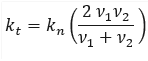
where ri is the physical radius of element i. A single value for the overall normal stiffness of the bond kn is then calculated as:

and the corresponding tangential stiffness kt is calculated as:
With these bond stiffnesses defined, the associated normal contact force of the bond is calculated by:

where δn is the normal overlap of the contact.
This normal contact force is then damped according to the following:
![]()
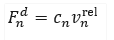
where vnrel is the magnitude of the normal component of the relative velocity between the two contacting elements and cn is the damping coefficient given by:
![]()
where

e is the coefficient of restitution, m* is the equivalent mass:

and mi is the mass of element i:
The magnitude of the tangential contact force is calculated as:
![]()
where δt is the tangential overlap of the contact. The tangential contact force component is not damped.
Calculating the force with inactive bonds
Consider the constitutive equations and associated failure criteria for when the bonds break or if they were never created.
The failure criteria for the bonds can be defined as follows:

where Rn and Rt are the normal and shear strengths (defined by the user). The bond will break under one of the following conditions:
- The bond is under tension and the magnitude of the normal component of the contact force exceeds the defined normal strength.
- The bond is under either tension or compression and the magnitude of the tangential component of the contact force exceeds the defined shear strength.
When under compression, bonds cannot break because of an excessive normal contact force. This is what gives the model its elastic behavior.
In the absence of any bonds - if they were never formed or previously met one of the failure criteria and broke - the normal contact force is calculated only when the contacting elements are compressed. In this instance, the normal contact force and associated damping force remain the same as defined previously:
and
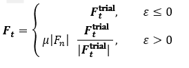
but the tangential contact force is now calculated by first calculating a trial state:
![]()
and subtracting the friction force as given by the Coulomb friction law:
![]()
where μ is the static coefficient of friction.
The actual tangential contact force Ft is then calculated as:
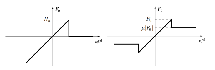
The model yields the following force-displacement behavior:
Using the Linear Elastic Bonding Model
To use the Linear Elastic Bonding Model, you must first add it to the Physics of a given EDEM simulation and then configure as required.
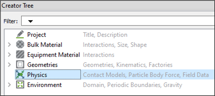
- In the Creator Tree, select Physics.
-
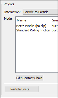
Select Particle to Particle and/or Particle to Geometry from the Interaction dropdown list.
-
Click Edit Contact Chain at the lower section of the Physics panel.
-
Select No Base Model from the Base Model dropdown list.
-
Under Plug-in Models, select the LinearElasticBonding checkbox.
-
Click OK.

The plug-in is displayed in the Model panel. -
Select the plug-in and click the
 icon in the lower-right section of the Physics panel to configure it.
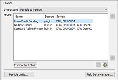
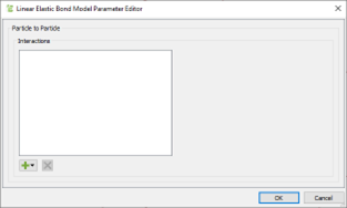
The Linear Elastic Bond Model Parameter Editor is displayed.
As long materials are defined in your simulation, the  icon will be enabled.
-
Click the
icon to view a list of all possible interactions for Particle to Particle or Particle to Geometry contacts.
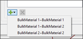
-
Select the interaction you would like to set up bonds for.
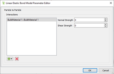
The dialog box displays two parameters on the right-hand side. -
Specify values for Normal Strength and Shear Strength of the formed bonds.
To understand how these parameters determine the model behaviour, see the Theory section. -
Once you have entered values for the interaction, click OK and repeat the same steps for other interactions you would like to set up bonds for.
Post Processing
Bond properties are post-processed, as with EDEM's Bonding and Bonding V2 models, by looking at the properties of the related contacts rather than using EDEM's legacy Bond properties. The same is true for bond visualization, which requires visualizing the pertinent bonds and applying the proper coloring.
After a simulation has run with the Linear Elastic Bonding Model enabled, you can post process the behavior of the model using the following custom properties:
Contact custom properties
- customInitialOverlap – Indicates the initial value of the overlap of the elements in contact before the bond is formed.
- BondStatus – Indicates the property that determines whether the bond exists or not. A value of 1.0 indicates a successful bond has been formed and is currently active. A value of -1.0 indicates that the bond has been broken. A value of 0.0 indicates a bond was never formed.
- customShearForce – Indicates the Shear force acting on the contact.
Particle custom properties
- customBondsInitial – Indicates the number of bonds that an element has after the initial bond formation time.
- customBondsDamage – Indicates the metric for the damage to the bonds for a given particle, calculated as:
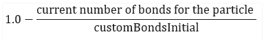
A value of 0.0 indicates all initial bonds are still formed. A value of 1.0 indicates all initial bonds are now broken.
Simulation custom properties
- customTotalBonds – Indicates the total number of bonds in the simulation at the current Time Step. This will be at its maximum value the Time Step after the bonds are formed and will be decremented as bonds are broken.
- customBrokenBondsNormal – Indicates the total number of bonds in the simulation that have broken due to excessive normal force.
- customBrokenBondsShear – Indicates the total number of bonds in the simulation that have broken due to excessive Shear force.
(c) 2023 Altair Engineering Inc. All Rights Reserved.