Material Model Editor
It provides an easy-to-use interface for specification of the distribution of model particles (created in the Particle Shape Editor) and size distribution, selection of the desired contact models, definition of the contact model parameter values such as Coefficient of Restitution, static and rolling friction.
The EDEM Material Modeler includes a range of contact models including Hertz-Mindlin (no slip), Linear Spring, Linear Cohesion (V2), JKR cohesion, Bonded Models and Surface Wear Models.
The DEM Material Models created in the Material Model Editor are saved to a database that can be accessed and shared with a team of engineers. By building-the know-how required to define a fit-for-purpose material into the DEM Material Model, even those who are not experts in DEM are able to use the models to gain the valuable insight into the performance of bulk materials handling equipment.
Accessing the Material Model Editor
- From the Start menu, open EDEM with Material Modeler.
- On the Toolbar, select Material Modeler > Material Model Editor.
- Toolbar and Menu Bar.
- Materials.
- Material Properties and Interactions tabs.
Toolbar
| Icon | Name | Description |
|
|
Reload | Reloads the database. |
|
|
Save | Saves the database. |
|
|
Add material | Adds a new particle. |
|
|
Remove material | Removes the current material. |
|
|
Rename material | Renames the current material. |
|
|
Copy material | Creates a copy the current material. |
|
|
Open GEMM Wizard | Click to open the GEMM Wizard.2233 |


Menu Bar
File Menu
- Reload
Reloads the database, any unsaved changes are lost. - Save
Saves the current database. - Import
Selecting this option allows you to import the contents of an EDEM Material Model database file into an existing library of calibrated materials. An EDEM Material Model file has an ‘.emm’ file extension.
It is advisable to backup any existing materials before importing. - Select File > Import.
You will be prompted to create a backup. See Backup command for more details.
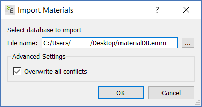
- Click Browse to locate the database required to be imported.
The Overwrite all conflicts checkbox should be checked by default. In most cases, this will be sufficient for importing a database. You can uncheck it if there may be conflicts with material or particle names and they wish to decide what to do for each conflict that occurs during import. - Click OK.
If Overwrite all conflicts is checked, skip to point 6.
If Overwrite all conflicts is unchecked and there are conflicts between the database being imported and the existing database, you will be asked to resolve these conflicts manually. You will be given the choice of overwriting the existing database entry, or renaming the entry being imported.
For example, if you have a Category with the same name, the following options are available:
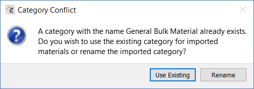
Use Existing indicates that all imported materials that belong in this category will be imported into this category. Rename means that users will have to choose another name for the category. Imported materials will go in this renamed category.For Material conflicts, the options Overwrite and Rename are displayed.
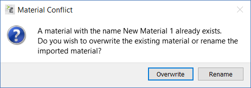
Overwrite will copy the data from the selected database over the existing database entries. All existing data for that material will be lost. Rename will rename the material being imported into the existing database. The original entry will remain and the imported material will be inserted under the new name. -
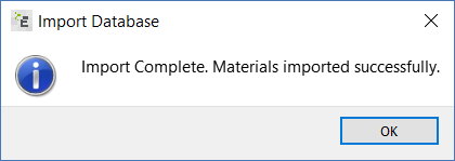
When the import is complete, a dialog box displays that the materials were imported successfully.
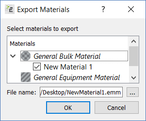
- Export. Export all or a subset of materials to be written to a new database file. When selected a dialog will appear where you can select which materials are to be copied to a new database file. You selects the materials to export, and any associated components of the DEM Material Model (for example, particles and templates) will also be exported.
- Backup. Backup the complete database to a new database file. You must specify the filename for the backup file. The filename will be automatically populated with the current database name, plus the data and time. The backup file must have the extension .emm.
- Quit. Quit the Material Model Editor. If there are unsaved changes, you will be prompted to save them. If changes are not saved, they will be lost.
Importing a database
Tools Menu
- Add Material
Adds a new material. Selecting this option will bring up a dialog where you can specify the new material name, and choose the category the material should be added to. The category chosen will determine whether it is a bulk material or an equipment material. - Remove Material
Removes the currently selected material from the database. - Rename Material
Renames the currently selected material. - Copy Material
Creates a copy the currently selected material. The material will stay in the same category. - Add Category
Adds a new category. This will display a dialog box where you can specify the category name and also select whether it is for bulk materials or equipment materials. - Remove Category
Removes the current category. - Rename Category
Renames the current category.
View Menu
- Toolbars
Show or hide the toolbars.
Materials
The Materials pane comprises a list of all the materials currently stored in the database. Selecting a material in the Materials pane will dictate what is shown in the Material Properties and Material Interaction tabs. Multiple materials and categories can be selected. When multiple materials or categories are selected, the Material Properties tab cannot be edited. This prevents the accidental change of multiple material properties at the same time. The Material Interactions tab can still be used and selecting multiple materials is useful in comparing the different parameter values for different materials.
Right-clicking on the materials list will show a popup menu that allows you to add, remove, rename, and copy materials; and also to add, remove and rename categories.
Material Categories
All materials within the Material Modeler are stored in categories. The category system defines whether a material will be available for use as an equipment, or as a bulk material in simulation.
When creating new materials, you should ensure that the appropriate category is selected.
Material Properties
The Material Properties tab is split into two sections - Element Properties and Particle Shapes. The Particles Section will only be displayed if a bulk material is selected. Equipment materials do not have particles associated with them. If more than one material is selected, then the Material Properties cannot be edited.
Element Properties
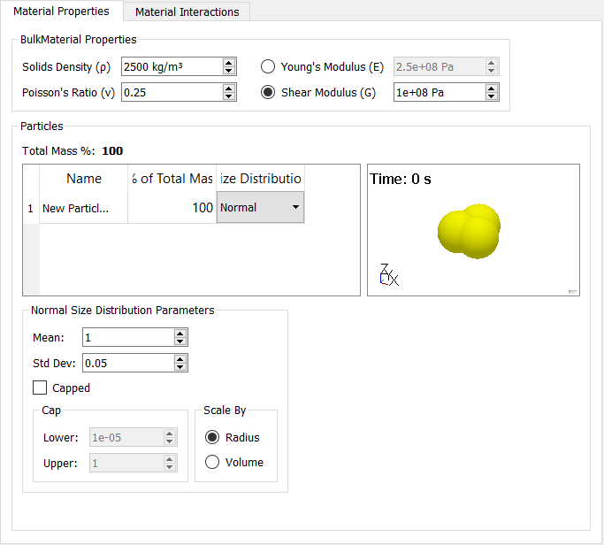
Here you can specify the Specific Density, Poisson's Ratio, and Shear Modulus or Young’s Modulus. The Shear Modulus and Young’s Modulus are dependent on one another so you can enter one and the other will automatically be calculated using Poisson’s Ratio.
Particle Shapes
In this section you can specify the particles that will be used to make up the bulk material. The section contains a table where you can add particles (created in the Particle Shape Editor) to a material. Above the table it shows the Total Mass % for that material. On the right there is a 3D viewer panel that shows the particle that is currently selected in the table. At the bottom the parameters for the size distribution for the currently selected particle are shown.
Particle Table
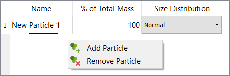
This table contains the particles that will be generated by a bulk material. If you right-click on the table, a menu will pop up that allows particles to be added or removed from a material.
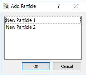
When you select Add Particles, a dialog box displays a list of all the available particles. There is no limit on the number of different particles that can be added to a material, however particles that have already been added cannot be added again.
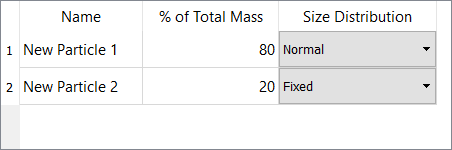
Once you have added the required particles, the next step is to determine the percentage of the overall bulk mass each particle will account for.
The table shows the Total % Mass for that material. This will be black if the values in the % of Total Mass column all add up to 100%, otherwise it will be shown in red to show that you should amend the values for 1 or more of the particles.
You can also specify a range of size distributions for each particle within the Size Type column. The size distributions available are: Fixed, Normal, Log Normal, Random, and User Defined. The size distributions parameters can be changed below the table.
See the Size Distribution Parameters section for more details.
Size Distribution Parameters
Size Distribution Parameters are displayed below the particle table. A different set of parameters will be shown, depending on what particle in currently selected in the table and what size distribution is selected for that particle. These parameters let you choose what size distribution will be assigned to the material particles when a bulk material is generated.
You define the default size of any particle in the Particle Shape Editor and bulk materials will produce size distributions based on this default size. All sizes are defined as factors of the originally specified size. There are five size distributions that can be applied to selected particles.
-
Fixed
All particles are of an equal size: For example, if the size ratio is set to 2, all particles will be twice the standard radius. - Random
Particle radii are randomly sized within a set size range: For example, with a minimum size of 0.5 and a maximum of 1.5, particles no smaller than half and no bigger than one-and-a-half times the size of the standard size are produced. - Normal
Particle radii have a Normal Distribution. The average (mean) particle radius or volume and the standard deviation must be defined. The mean and standard deviation should both be normalized, i.e. the mean is the ratio of the mean to the input particle radius or volume and similarly for the standard deviation. Use the capping options to cap the maximum and minimum particle sizes. - Log-Normal
Particle radii have a Log-Normal Distribution. The average (mean) particle radius or volume and the standard deviation must be defined. The mean and standard deviation can be defined using a logarithmic or linear scale. With a logarithmic scale, the input values are exponential functions. For example, a mean value of 1 in the logarithmic scale denotes an actual scaling of 2.718 in the linear scale.
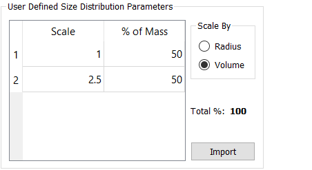
The mean and standard deviation should both be normalized, i.e. the mean is the ratio of the mean to the input particle radius or volume and similarly for the standard deviation. - User Defined
Particle radii have a range of sizes applied. Here the user can specify a number of different sizes and what percentage each of the chosen sizes will be used. Additional sizes (“Scale”) can be added or removed by right-clicking in the table. The % of Mass column shows what percentage of the total distribution will be defined for that particularly particle. To the right side of the table the Total % provides the total amount of the mass distribution that has been allocated. This value must equal 100%.
Material Interactions
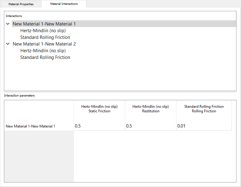
The Material Interactions tab enables the user to define how a material will behave in a simulation when it comes into contact with both itself and other materials. Adding interactions between materials involves the selection of which contact models are to be used, and the specification of the required parameter values for the selected model.
The Material Interactions tab consists of two parts: at the top is an Interactions list for the selected materials and at the bottom a table for the Interaction Parameters, which displays the parameter values that are currently assigned to the interaction properties.
Interactions
You may not want to add interactions with every material in your database. However, the interactions between materials must be defined for them to be used together in a simulation. If materials will never be used together in the same simulation, then the user does not need to define these interactions.
When a material, or materials, are selected the Interactions list will show the combinations of materials names that have interactions defined for the selected material. The list of interaction combinations can be expanded to show the contact models that are used for each specific interaction.
When the user selects a combination of material names, or an individual interaction, from this list, the relevant details will be shown in the Interaction Parameters table along with the values for each parameters. The content of the list will also depend on what materials are selected in the Materials pane. All of the defined interactions, for each selected material, will be shown.
Adding Interactions
You can add interactions by right-clicking the Interactions list and using the popup menu.
-
Select the material for which interactions are required.
-
Right-click and select Add Interaction.
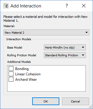
A dialog box prompts you to choose the following: a) the second material for the interaction and , b) the physics contact models to use when the materials contact each other.
The first material in the interaction pair will always be the material originally selected in the Materials pane. The second material can be selected from the dropdown list. The list will not contain materials that already have a defined interaction with the first material. You cannot add interactions between two equipment materials.
Once the material has been selected you must select the contact models to use. Interactions must consist of a base model, and a rolling friction model. Then other additional models can be added. The additional models available will be dependent on what materials are selected. For example, Archard Wear is included when one equipment material is selected. -
After selecting the required contact model(s), click OK to add the interactions to the Interactions list.
Interaction Parameters
The input parameters and corresponding values for the currently selected interactions will be shown in the Interaction Parameters table. Each row in the Interaction Parameters table refers to the interactions defined for two materials. Each column is used for listing the names of the contact model parameters. The column headings have the contact model name first, then the parameter name, and then the units (if applicable).
You can Ctrl-clickm to select multiple interactions simultaneously and all the relevant input data is shown in the Interaction Parameter table. The column names that are shown will vary depending on a) what contact models are used in an interaction pair, and b) on what interactions are selected in the list above.
Changing Parameter Values
Values can be changed by double-clicking on the table cell and typing in the new value.
Where multiple interactions have been selected in the list and multiple contact models are in use, there may be cells in the table which do not have values in them. These cells cannot be edited because the contact model is not in use by those two materials. For example, in the figure below, the Archard Wear Constant cell is empty for the first row, because the Archard Wear contact model isn’t added to the interaction between those two materials.
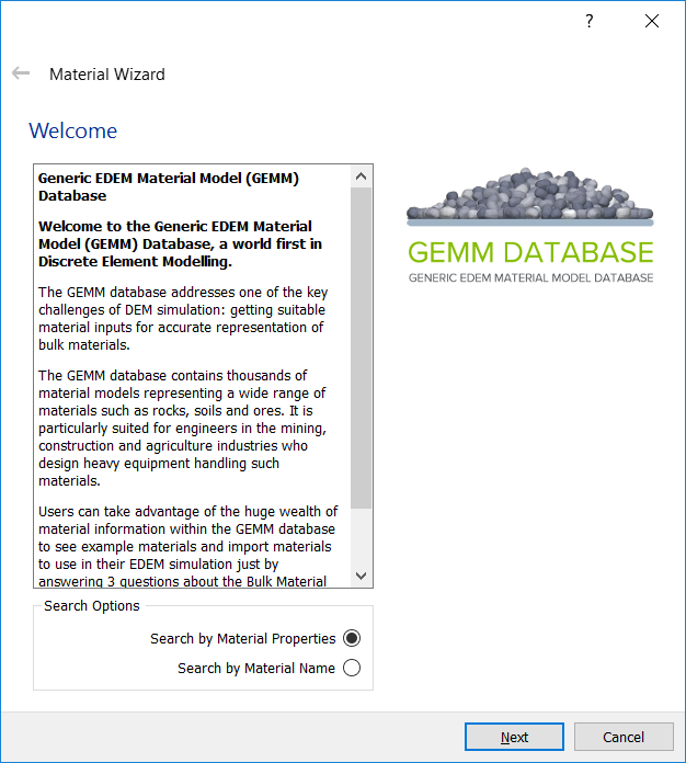
The GEMM Wizard
The GEMM database addresses one of the key challenges of DEM simulation: getting suitable material inputs for accurate representation of bulk materials.
The GEMM database contains thousands of material models representing a wide range of materials such as rocks, soils and ores. It is particularly suited for engineers in the mining, construction and agriculture industries who design heavy equipment handling such materials. You can take advantage of the huge wealth of material information within the GEMM database to see example materials and download input decks to use in their EDEM simulation just by answering 3 questions about the Bulk Material and one question about the Equipment Material.
To use the GEMM Database, click Open GEMM Wizard in the Material Modeler toolbar.
The first page is a description of the database, read, select Search by Material Properties and then click Next to answer the three questions on the particle Bulk Material behavior.
-
What scale is your application?
The GEMM Database contains several different sets of materials which are designed to cover a range of different material sizes. Each one has a size distribution based around a median value.
If you are not sure which size distribution to choose, start with the largest and test it on the application. It is faster to work with a test case where the particles are too large than it is to work with a case where they are too small because - with a large scale material - the particle count will be lower and therefore the simulation will progress quickly. If the particles are too small it can take a long time to fill a volume instead of progressing with the simulation.
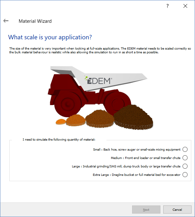
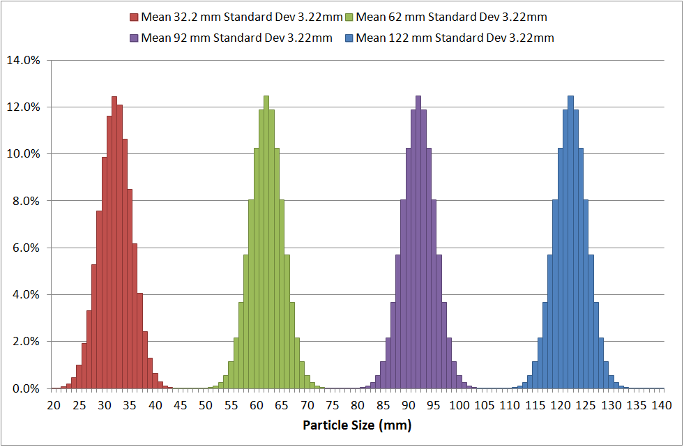
The actual size ranges used in the GEMM database are shown as follows:
-
What is the Bulk Density of your particle material?
Material Bulk Density is the ‘mass of the material (+ moisture content)’ / ‘volume of the material as whole. If The interface allows the user to pick a material Bulk Density within a range. If the real particle material Bulk Density lies close to the edge of one of the ranges this can be modified later following generation of the material file.
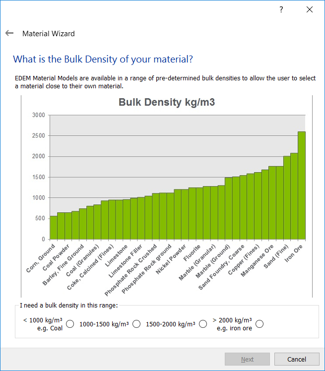
If a closer match to the bulk density is required, then you can perform a small study with variations of the material Solids Density using the provided GEMM material as a starting point.
-
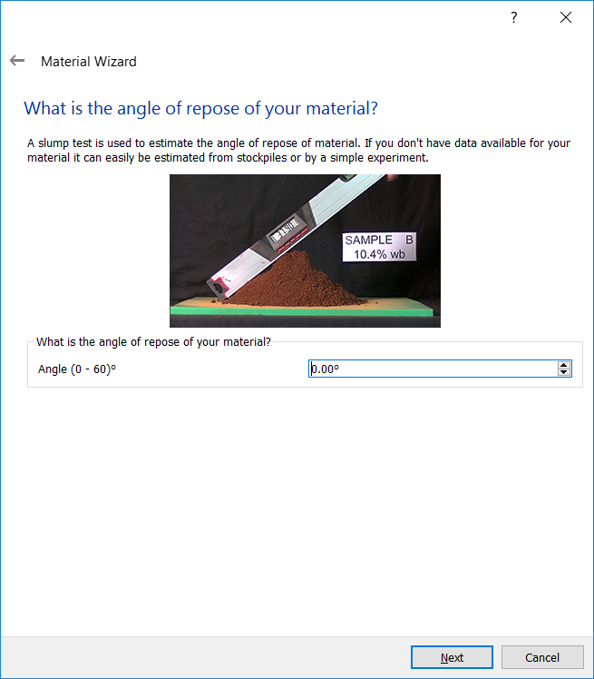
What is the angle of repose of your particle material?
The angle of repose is a commonly available measure of material that is contained in standard test data. Even if such data is not available in existing material data reports, it is a quantity that can be measured in a relatively easy way without specialist equipment (for example, observing the angle of a stockpile). Finally, if there is no access to any testing reports or on-site data, then it is a quantity that is relatively easy to estimate based on engineering experience.
It is difficult to measure an angle of repose to a high accuracy so it is usually treated as an approximation to the material behavior rather than defining it completely. For this reason the material model provided by the GEMM Database should be used as a guide or starting point, and the user must be aware that differences in behavior might still occur.
An example of the angle of repose test is as follows:
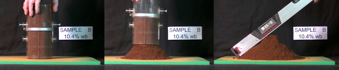
The maximum value for Angle of Repose in the GEMM database is 60 degrees, any materials with angles higher than this should be calibrated separately, the lowest angles can be found between 20 and 30 degrees.
Once these 3 questions are answered a list of 10 materials is provided. These materials are the 10 closest matches based on the answers that have been given.
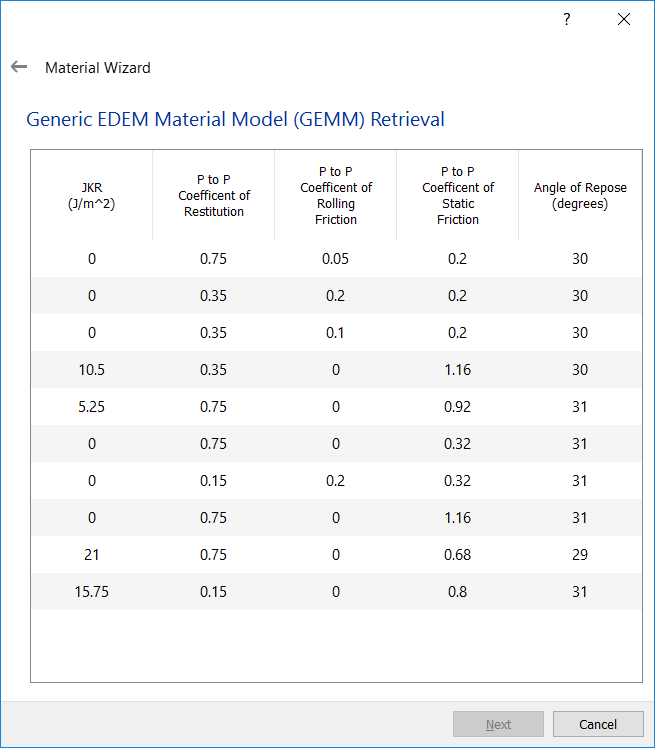
You can select any one of these materials - the top material is the closest match to the input angle of repose. However, other materials can also be chosen from the list.
P to P refers to the Particle to Particle values of Restitution, Static Friction and Rolling Friction. The JKR value is the cohesive energy value for this material. A ‘sticky’ material will tend to have a higher JKR value than a non-sticky material even if both materials have the same angle of repose. High JKR cohesion values are best paired with higher coefficients of restitution to avoid overly damped simulations.
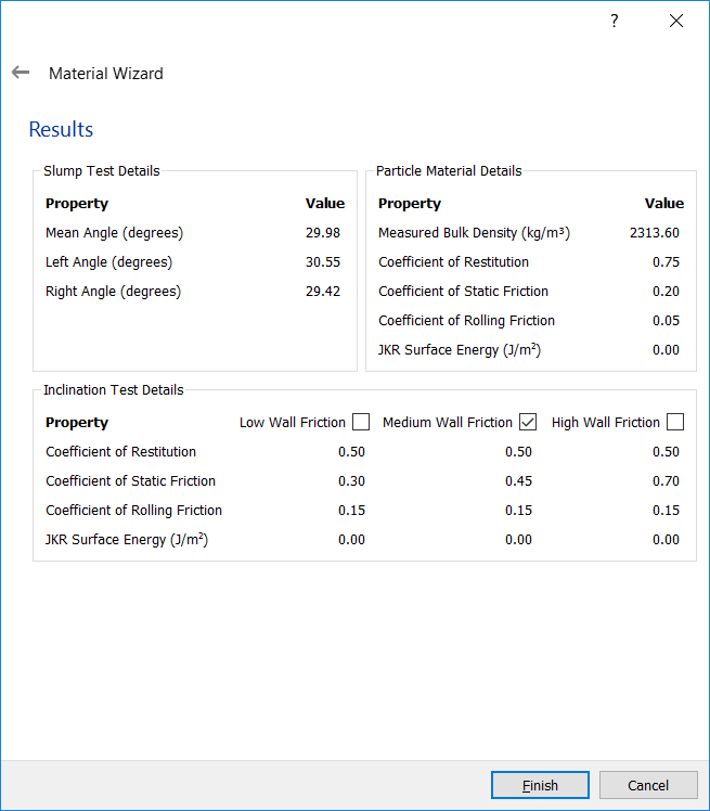
Once a material has been selected, the material details are provided. This includes the measured material Bulk Density value for this specific material.
You can then select the following Equipment Interactions for this material:
- Low Friction
- Medium Friction
- High Friction
Once the interactions are selected, click Finish to add the Bulk Material to the simulation. This material is added to the following areas:
- Bulk Material
- Properties
- Shape
- Size Distribution
- Interactions (Bulk Material - Bulk Material and Bulk Material - Equipment Material)
Medium friction is designed around a material such as Steel. The material friction is based around an Inclination Test. A sample of the Bulk Material is placed on a flat plate, the plate is then inclined until the material begins to slide. A material with a low Bulk Material angle of repose will slide at a lower inclination angle than a material with a high Bulk Material angle of repose. As such, the Bulk Material is characterized as Low Angle (Repose Angle less than 35 degrees), Medium Angle (Repose Angle Greater than 35 degrees but Less than 45 degrees) and High Angle (Repose Angle Greater than 45 degrees).
The Equipment Interactions are then provided based on the following table.
| Material Type | Equipment Type | Static Friction (p-g) | Rolling Friction (p-g) | JKR Cohesion (p-g) | Inclination Test Reasults (average angle) |
| Low angle | Low Friction | 0.3 | 0.15 | 0 | 21 |
| Low angle | Medium Friction | 0.45 | 0.15 | 0 | 27 |
| Low angle | High Friction | 0.7 | 0.15 | 0 | 34 |
| Medium angle | Low Friction | 0.45 | 0.15 | 0 | 28 |
| Medium angle | Medium Friction | 0.7 | 0.15 | 0 | 35 |
| Medium angle | High Friction | 1 | 0.15 | 0 | 39 |
| High angle | Low Friction | 0.7 | 0.15 | 0 | 37 |
| High angle | Medium Friction | 1 | 0.15 | Low | 46 |
| High angle | High Friction | 1.7 | 0.15 | High | 49 |
(c) 2023 Altair Engineering Inc. All Rights Reserved.