Intra-Particle Spray Coating Guide
Some of the advantages are:
- It runs in the analyst, so different spray configurations can be analyzed without re-simulating the deck (post-processing).
- It provides information about the average coating distribution for each face on the surface of the particle (intra-particle).
Limitations
- Only polyhedral particles are currently supported.
- Spray coating uses only data from saved timesteps. Use a small save interval for accurate results.
- The ray-tracing approach assumes that droplets reach their target instantly; influences such as gravity are not considered.
How it works
The spray coating tools use ray tracing to calculate the path of coating material droplets. When a droplet is ejected, it is represented as a straight line (or 'ray') originating from the nozzle. The first intersection with a particle along this path is calculated, and the droplet mass is deposited as a coating on that particle. Intersections are mapped to a specific face on the particle mesh, so that the distribution of coating over the particle surface is also recorded.

Spray paths are uniformly distributed in a cone formation:

Usage
The spray coating analysis can be added to a simulated EDEM deck with polyhedral particles. For best results, the deck should use frequent saving so that the motion of each particle is captured in detail. Also make sure that the particles have sufficient faces to capture the intra-particle coating distribution at the desired level of detail.
- Switch to the analyst.
- Right-click Spray Coating Analysis in the analyst tree, select Add Spray Coating Item, and give the coating a meaningful name. A set of spray coating options becomes available:

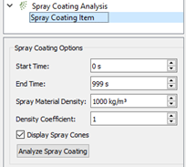
The Start Time and End Time determine the simulation time range in which spray coating should be applied. The Spray Material Density specifies the density of the coating substance, which will only be used to calculate coating volume and thickness.
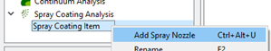
The Density Coefficient is a dimensionless number that controls the number of ray-tracing rays. In general, higher numbers mean a slower but more detailed analysis. A density coefficient of 1.0 is roughly equivalent to one ray per particle face for a particle at the furthest distance from the spray. - Right-click the spray coating item and select Add Spray Nozzle. Multiple nozzles can be added. Some more options are configured per-spray:
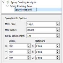
The Mass Flow defines the rate at which this nozzle outputs coating material.
The Max Angle defines the full angle of the nozzle’s spray cone, from one edge to the other. This must be more than 0deg (spray leaves the nozzle in a straight line) and less than 180deg (spray leaves in any direction, except backwards).
The Spray Zone Length defines the maximum distance from the nozzle that spray particles can travel. This is used to calculate the required ray density, and particles outside this range are ignored. It is important to make this length long enough to capture all particles, but not longer than is necessary or performance will drop due to the increased ray density.
The Origin and Rotation settings control the position and angle of the spray nozzle. - To begin the spray coating analysis, click Analyze Spray Coating in the spray coating options.
A console window displays the progress of the calculation. The button also changes into a Cancel button, which can be used to end the analysis early. Partial results will still be saved in this case.
Results
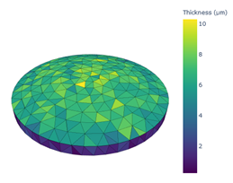
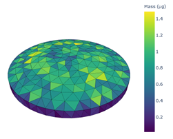
When the analysis is complete, plots of the average intra-particle coating distribution will be automatically displayed in the default web browser. These plots are also saved as .html files, located next to the simulation’s .dem file:
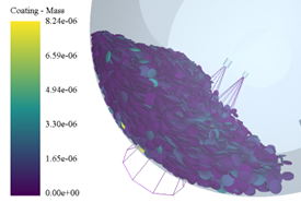
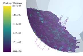
The analysis also adds custom properties to the deck. They display the coating mass and thickness as applied to each particle.
The custom property values are in base SI units (kg and m respectively):
(c) 2023 Altair Engineering Inc. All Rights Reserved.